


PowerQUICC II CPM Initialization
72 Interphase Corporation
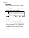
Final Result of SIxAMR (line 1 to 2 and line 3 to 4) and SIxBMR (line 2 to 1 and line 4 to
3) registers is 0x0169.
NOTE
When a TDM is not used, it is not necessary to initialize the corresponding SIxMR
register.
By setting CMXSI1CR to 0x30, CLK1 is assigned as input clock to TDMa1, CLK3 is
assigned as input clock to TDMb1, CLK13 is assigned as input clock to TDMc1, and
CLK15 is assigned as input clock to TDMa1
By setting CMXSI2CR to 0x00, CLK1 is assigned as input clock to TDMd2, CLK3 is
assigned as input clock to TDMc2, CLK13 is assigned as input clock to TDMa2, and
CLK15 is assigned as input clock to TDMb2.
See Boot Firmware sources: tst\c\pqtdm.c - Function vPQTDM_SI_Init_PQII.
PC(31) must be configured as CLK1 input, PC(29) as CLK3 input, PC(19) as CLK13 input,
and PC(17) as CLK15 input.
See Boot Firmware sources: sys\h\4538.h (search CLK1, CLK3, CLK13 and CLK15).
Other TDMx signals also have to be configured on the parallel ports.
See Boot Firmware sources: sys\h\4538.h.
Assign TDMA1_L1RSYNC, TDMA1_L1RXD, and TDMA1_L1TXD to PA(6), PA(8),
and PA(9) respectively.
Assign TDMB1_L1RSYNC, TDMB1_L1RXD, and TDMB1_L1TXD to PD(10), PD(12),
and PD(13) respectively.
Assign TDMC1_L1RSYNC, TDMC1_L1RXD, and TDMC1_L1TXD to PD(26), PD(27),
and PD(28) respectively.
Assign TDMD1_L1RSYNC, TDMD1_L1RXD, and TDMD1_L1TXD to PD(23), PD(24),
and PD(25) respectively.
Assign TDMA2_L1RSYNC, TDMA2_L1RXD, and TDMA2_L1TXD to PD(20), PD(21),
and PD(22) respectively.
Assign TDMB2_L1RSYNC, TDMB2_L1RXD, and TDMB2_L1TXD to PB(29), PB(30),
and PB(31) respectively.
Assign TDMC2_L1RSYNC, TDMC2_L1RXD, and TDMC2_L1TXD to PB(24), PB(26),
and PB(27) respectively.
Assign TDMD2_L1RSYNC, TDMD2_L1RXD, and TDMD2_L1TXD to PB(20), PB(22),
and PB(23) respectively.
NOTE
TDMbx, TDMCx, and TDMdx parallel port pins must be configured as general
purpose output pins.
See Boot Firmware sources: sys\h\4538.h.