


Chapter 5: Connectors and Front Panel
4538 Hardware Reference Manual 109
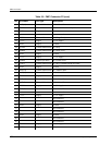
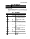
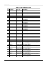
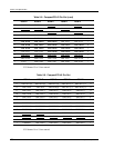
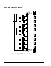
Signals printed in bold in Table 5-8 and Table 5-9 shall be routed to the corresponding PMC
connector (used on 6435 RTM).
Signals printed in italics and underlined in Table 5-8 and Table 5-9 shall not be used on the
carrier card. They should be routed to the corresponding PMC connector.
Signals followed by a (*) sign in Table 5-8 and Table 5-9 may be driven by the carrier card
(No connection on the 6435 RTM). If switch mode is not supported by the carrier card, they
should be routed to the corresponding PMC connector.
J5 A1 pin: TMRSNT: 6435 includes a 100 Ohm pull-up to 3.3 V (may be used by the carrier
card to detect 6435 presence).
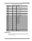
We recommend routing every other signal as indicated in Table 5-8 and Table 5-9 for future
compatibility.
Custom Carrier Card
Customers who want to implement a 4538 "rear access" on configurations other than those
described above will need to design their own line interfaces. For these customers,
Interphase can provide additional information, such as schematics and a bill of material for
these line interfaces.