


3
4538 Hardware Reference Manual 69
3Programming the Peripherals
Overview
This chapter provides information specific to the 4538 board for peripheral programming.
Its initial purpose is not to detail how to program the peripherals themselves, for which the
developers should refer to the manufacturers data sheets. However, for tricky peripherals,
such as T1/E1/J1 framers, some important register programming is detailed. For more
details, refer to the 4538 Boot Firmware sources provided with the CD-ROM and
referenced (in italics) in this chapter. See also the 4538 Built-In Self Test and Monitor
Manual
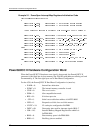
PowerQUICC II CPM Initialization
The different functions on the CPM are used as follows:
• MCC1 connected to SI1, using TSA1 (128 time slots)
• MCC2 connected to SI2, using TSA2 (128 time slots)
• FCC3 connected to MII interface for Fast Ethernet
• SMC1 used for TTY interface
Serial Interfaces and Time Slot Assigner Initialization
In the CPM, the Time-Slot Assigners (TSAs) are parts of the Serial Interfaces (SIs).
Most TSA programming is done in two 256x16bits SIx RAMs per SI: one for receive and
one for transmit. These SIx RAMs are in the PowerQUICC II internal registers area, they
are not a part of the PowerQUICC II internal dual-port RAM. The programming of each
entry in the SIx RAM determines the routing of a group of serial bits.
See Boot Firmware sources: tst\c\pqtdm.c - Functions vPQTDM_SI_Init_PQII (Disable all
TDM and initialize clock route that defines connection of SIx to the clock sources) and
vPQTDM_SI_Init_PQII_PT (Initialize SIx for pass-through mode test),
vPQTDM_SI_Init_PQII_SW (Initialize SIx for switched mode test),
vPQTDM_SI_Init_PQII_MUL (Initialize SIx for multiplexed mode test),
vPQTDM_SI_Init_PQII_IND (Initialize SIx for independent mode test).
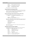
TDM Busses in Multiplexed Direct Mode and in Switched Mode
According to the TDM busses configuration (VHH7'0%XV&RQILJXUDWLRQV on page 34), the
SI1AMR register must be set as follows:
• Reserved = 0: This bit should be cleared.
• SADx = 000: Starting bank address for the RAM of TDMa. 000 for first bank, first
32 entries.
• SDMx = 00: SI Diagnostic Mode for TDMa. 00 means normal operation.