


Chapter 1: Hardware Description
4538 Hardware Reference Manual 3
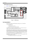
• Three Fast Serial Communications Controllers (FCCs). One is used to control the
Ethernet Media-Independent Interface (MII).
• Four Serial Communication Controllers (SCCs)
• Two Serial Management Controllers (SMCs)
• A debug serial port
• A Serial Peripheral Interface (SPI)
• Four timers and an interrupt controller
PowerQUICC II Resets
Once the card is powered-up and the power stabilized, the PowerQUICC II enters into a
sequence where it will define certain vital parameters, such as the type of its bus and the
PLL multiplication factors. Then it will wait for various conditions, such as PLL
stabilization and PCI reset signal de-asserted, before booting.
The PowerQUICC II is controlled by three reset signals:
• –PORESET: Power-on reset
• –HRESET: Hardware reset
• –SRESET: Software Reset
When –PORESET is activated, this also activates –HRESET and –SRESET. –PORESET
is the strongest reset. When –HRESET is activated, this also activates –SRESET. When
–SRESET is activated, it does not interfere with the other resets (–SRESET is the weakest
reset).
A power supervisor controls the MPC8260 input signal –PORESET. It activates
–PORESET (0) when the power is not stabilized (at power-up or during power failures).
The –PORESET is maintained active for 150 ms after stabilization of the power.
After –PORESET is de-asserted (set to 1), the MPC8260 waits 1024 input clock cycles and
samples the MODCK[1:3] bits, which define the default clock multiplication factor and
input clock used for the SPLL. The MPC8260 starts its PLL at this time. It maintains
–HRESET and –SRESET asserted while the PLL is not locked.
Through its pin –PB_RESET, the PowerSpan also maintains –HRESET asserted as long as
the PCI reset signal is activated.
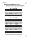
PowerQUICC II –RSTCONF pin is tied to ground, indicating that the MPC8260 is the
configuration master. At the rising edge of –HRESET, the MPC8260 generates 64-bit reads
into its boot memory (the FLASH) with address starting at 0 and incrimented by 8. The first
eight bytes set its Hard Reset Configuration (for detailed initialization see PowerSpan
Hardware Configuration Word on page 59).
The PowerSpan has no dedicated pin to control the PowerQUICC II hard reset signal
–HRESET and soft reset signal –SRESET. Instead, two of its interrupt pins, –INT2 and
–INT3 respectively, configured as an output are used. These interrupt are controlled with
doorbell bits (see Hardware and Software Resets Through the PowerSpan on page 21).