PowerQUICC II Hardware Configuration Word
62 Interphase Corporation
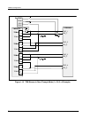
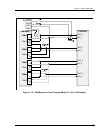
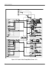
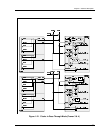
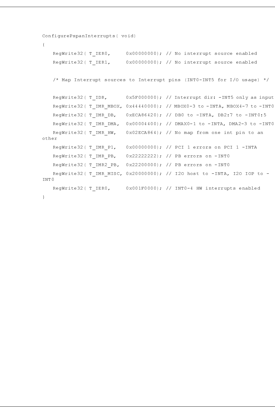
Example 2-1. PowerSpan Interrupt Map Registers Initialization Code
PowerQUICC II Hardware Configuration Word
When the PowerQUICC II hardware reset signal is de-asserted, the PowerQUICC II
generates 64-bit reads into its boot memory (the FLASH) with addresses starting at 0 and
incremented by 8. The first eight bytes set its Hard Reset Configuration.
For the 4538, the PowerQUICC II Hard Reset Configuration is (must be):
• EARB = 0: Internal bus arbitration
• EXMC = 0: The internal memory controller is used
• CDIS = 0: The core is active
• EBM = 1: 60x-compatible bus mode
• BPS = 01: 8-bit boot port size
• –CIP = 0: Initial vector table base address is 0xFFF0 0000
• ISPS = 0: Responds as 64-bit slave to 64-bit masters
• L2CPC = 10: L2 cache pins configured as BADDR
• DPPC = 00: Data parity pins used for interrupt signals IRQ1
–7
• ISB = 110: Internal Memory Mapped Register base address is
0xFF00 0000
• BMS = 0: Boot memory space is 0xFE00 0000
• BBD = 0: Bus Busy pins are enabled


