


4
4538 Hardware Reference Manual 87
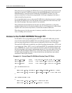
4Accessing the 4538 on the PCI Side
PowerSpan Configuration by the PCI Host
Several elements of the PowerSpan are automatically configured at power-up by the
hardware, or by the PowerQUICC II. However, some PCI-specific settings have to be done
by the PCI host.
PCI Configuration
The card is identified through its Interphase Vendor ID (0x107E) and its PCI device ID
(0x9070). Its PCI configuration is set up by the PCI host at its power-on or by the “high
availability” operating system if the 4538 has been hot inserted.
Interrupt Pin Configuration
The set up of the PowerSpan Interrupt Map registers is normally done by the PowerQUICC
II when it boots, so they should not need to be reconfigured, except if the card has not yet
received a valid boot firmware.
PCI-to-Local Window Configuration
When accessing through a PowerSpan PCI-to-local window, this window must have been
enabled in the I
2
C serial EEPROM, in order to allow the CompactPCI host to detect it at
system power-on or after hot insertion of the board, and map it in the PCI space.
The corresponding PowerSpan register PCI Target Image Control Register must also have
been initialized with the Image Enable bit set (IMG_EN=1) and the address translation
mechanism enabled (TA_EN=1).
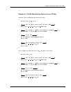
Controlling the 4538 Hardware and Software Resets
PowerSpan interrupt pins –INT2 and –INT3 are used as output ports to control the
MPC8260 hardware reset signal –HRESET and software reset signal –SRESET
respectively. They are conventionally associated with doorbell bits 4 and 5 respectively. The
PowerSpan Interrupt Map registers must have been correctly initialized before (see
PowerSpan Configuration by the PCI Host on page 87).
During a power-up sequence, –HRESET and –SRESET are first activated and then
deactivated once the PCI bus reset signal is deactivated. This allows the PowerQUICC II
to boot without any host intervention, just after the end of the PCI reset.