


The Ethernet Port Initialization
84 Interphase Corporation
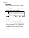
Transmit Pulse Shape
For each type of Line Build-Out (LBO), the shape of the transmit pulse must be adjusted
through QuadFALC registers LIM0, LIM2, XPM0, XPM1, and XPM2 in order to comply
with FCC 68 or ANSI T1.403 (see Table 1-27 on page 31).
Line LED Control
For each T1/E1/J1 line, there is one green LED.
Each green LED is controlled through a QuadFALC pin (RPDi), allowing software or
hardware control. Each of these RPDi pins can be configured for one of seven different
functions. The selection is done in QuadFALC register PC4 (one for each pin). This gives
the ability to control the LED in different operations:
• When PC4 = 0x00, the green LED is OFF
• When PC4 = 0x30, the green LED is ON
• When PC4 = 0x70, the green LED is ON if synchronized to Rx line, OFF
otherwise.
The Ethernet Port Initialization
The Ethernet Line Interface Unit (LIU) is a INTEL LXT971A.
The LIU is connected to FCC3 through a Media Independent Interface (MII).
See Boot Firmware: sys\h\4538.h.
The LIU internal registers are initialized through MDC and MDIO Management pins.
These pins have to be manually manipulated through PC(25) and PC(26) pins. The LIU
PHY address is set to 0 (address pins are cabled to 0V).
See Boot Firmware: eth\c\lxtinit.c.
The TTY Framer Initialization
The TTY port is connected to an SMC1 framer that is used in UART mode. For SMC1
operation, MPC8260 port D pins 8 and 9 have to be configured properly.
See Boot Firmware: sys\h\4538.h.
SMC1 baud-rate generator is BRG7 - see BRG7 – TTY Baud-Rate Generator on page 73.
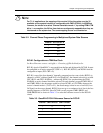
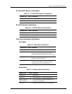
/,0'&2&7 )RU7RQO\±0+]UHIHUHQFHFORFNIRUWKH
'&25FLUFXLWU\SURYLGHGRQSLQ6<1&
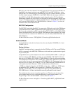
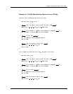
Table 3-10. Master Mode Initialization (cont)
Register Bit Value Comment