


Overview Power Supply Calculations
MRP-2001 & MRP-2001E PN 53040:A 4/16/2007 99
SECTION 5 Power Supply Calculations
5.1 Overview
This section contains instructions and tables for calculating power supply currents in alarm and
standby conditions. This is a four-step process, consisting of the following:
1. Calculating the total amount of AC branch circuit current required to operate the system
2. Calculating the power supply load current for non-fire and fire alarm conditions and calcu-
lating the secondary (battery) load
3. Calculating the size of batteries required to support the system if an AC power loss occurs
4. Selecting the proper batteries for your system
5.2 Calculating the AC Branch Circuit
The control panel requires connection to a separate, dedicated AC branch circuit, which must be
labeled FIRE ALARM. This branch circuit must connect to the line side of the main power feed
of the protected premises. No other non-fire alarm equipment may be powered from the fire alarm
branch circuit. The branch circuit wire must run continuously, without any disconnect devices,
from the power source to the control panel. Overcurrent protection for this circuit must comply
with Article 760 of the National Electrical Codes as well as local codes. Use 14 AWG (2.00 mm
2
)
wire with 600 volt insulation for this branch circuit.
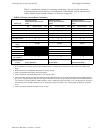
Use Table 5-1 , to determine the total amount of current, in AC amperes (A), that must be supplied
to the system.
TABLE 5-1:120 VAC Branch Circuit Requirements
Device Type
Number of
Devices
Current Draw
(AC amps)
Total Current per
Device
MRP-2001
or
MRP-2001E
1X
3.66
2.085
=
[ ] X =
[ ] X [ ] =
Sum Column for AC Branch Current Required =