


Master Programming Level Programming
MRP-2001 & MRP-2001E PN 53040:A 4/16/2007 53
Output Circuit MAP
Output Mapping (per input zone) allows the programmer/operator to assign the Output Circuits
that will be activated when a particular Input Zone or cross-zoned releasing group goes active.
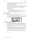
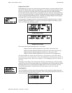
Pressing 3 for Output Circuit Map while viewing Edit Input Zone Screen #2 will display
screens which show the Output Circuits programmed to activate when the selected Input Zone
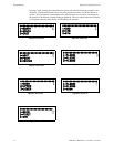
(or cross-zoned releasing group) is activated. Output Map Screen #1 displays the Output Type
Codes and programming for Output Circuits 1 through 3 and Output Map Screen #2 displays
the Output Type Code and programming for Output Circuit 4.
As an example, if Template 6 has been selected as the FACP Configuration [refer to "FACP
CONFIG (Application Templates)" on page 50], selecting the Output Circuit Map for Input
Zone 1 will display the following screens:
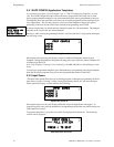
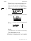
The screens indicate that when Input Zone 1 is activated:
Output Circuit #1 default programmed as Alarm NAC will activate (Yes)
Output Circuit #2 default programmed as Waterflow NAC will not activate (No)
Output Circuit #3 default programmed as Release 1 will activate (Yes)
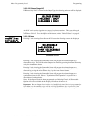
Output Circuit #4 default programmed as Supv Bell NAC is not mapped (N/A)
Note that the MAP may indicate that an Input Zone is programmed to a particular Output
Circuit but, if it is cross-zoned with one or more other Input Zones, all must be active in order to
activate the Output Circuit. Refer to the examples in "Circuit Mapping and Cross-Zoning" on
page 103.
The Output Circuit Map can be customized by selecting or deselecting any of the four output
circuits for activation. Pressing the number key corresponding to the selected output will toggle
the display between Yes for activation by the Input Zone to No for no activation. The new
customized programming is automatically saved by the panel as soon as it is entered.
Noun/Adjective
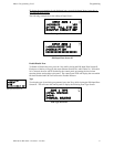
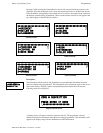
The Noun/Adjective selection allows the programmer to enter specific descriptors about the
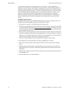
detector currently being programmed. Pressing 1 while viewing Edit Input Zone Screen #3 will
cause the following screen to be displayed:
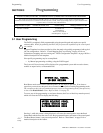
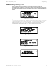
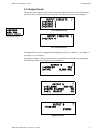
INPUT ZONE #
1=ENABLED
2=TYPE
3=OUTPUT CIRCUIT MAP
Edit Input Zone Screen #2
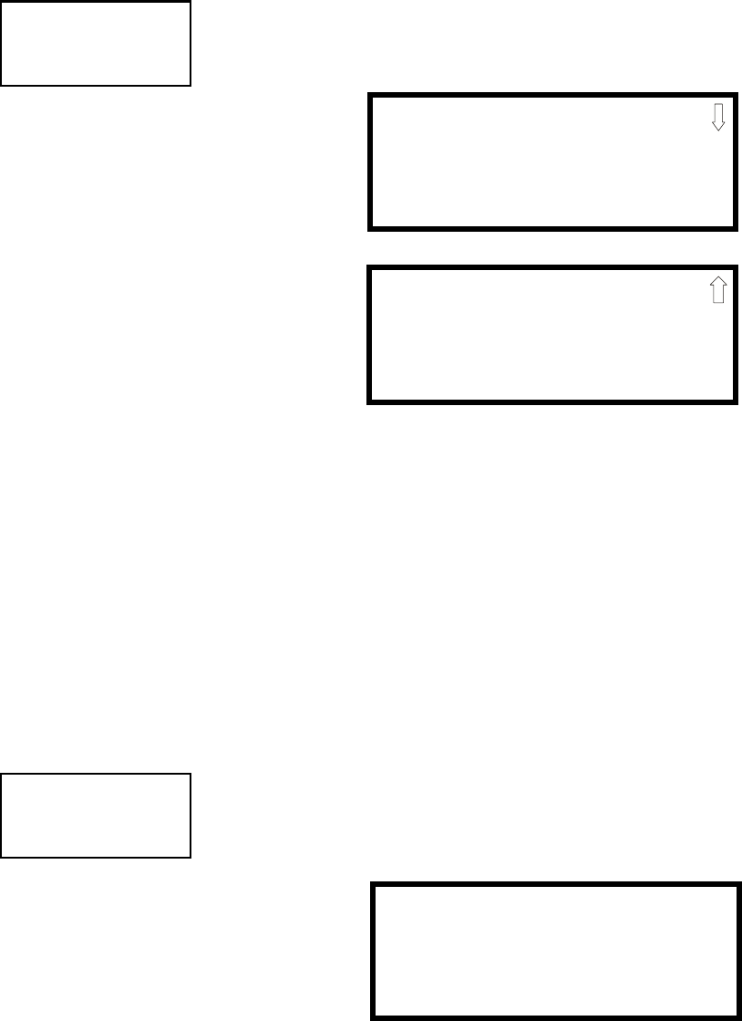
OUTPUT MAP ZONE 1
1=ALARM NAC YES
2=WATERFLOW NAC NO
3=RELEASE 1 YES
Output Map Screen#1
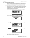
OUTPUT MAP ZONE 1
4=SUPV BELL NAC N/A
Output Zone Screen#2
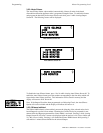
INPUT ZONE #
1=NOUN/ADJECTIVE
2=DESCRIPTION
*****************
Edit Input Zone Screen #3
1=STANDARD ADJECTIVE
2=STANDARD NOUN
Noun/Adjective Screen