


Programming Master Programming Level
64 MRP-2001 & MRP-2001E PN 53040:A 4/16/2007
In this example, since the cross-zoning for Release Circuit 1 (Zone 1) is being displayed, Yes is
shown for Zone 1 which is cross-zoned with Zone 2. Zone 2 displays Yes since it is cross-zoned
with Zone 1. The remaining zones display NO or N/A for no cross-zoning to Zone 1. By pressing
the number key corresponding to the desired zone, the display for that zone will toggle between Yes
and No indicating cross-zoning to Zone 1 or no cross-zoning to Zone 1.
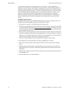
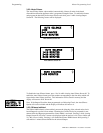
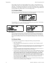
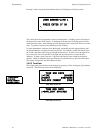
3.5.5 On-Board Relays
Pressing 2 while viewing Programming Screen #2 will allow the programmer to configure the three
main circuit board Form-C relays. The following screen will be displayed:
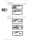
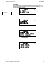
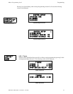
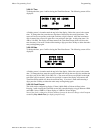
To program Relay 1, 2 or 3, press the number corresponding to the selected relay. The following
screens will appear for each relay to be programmed:
While viewing the selected screen, press the number corresponding to the desired relay type to
program the main circuit board relay. The choice will be stored in memory and the display will
return to the Relay Type Screen which will show the programmed type choice. Press the Escape
key to return to the Relays Selection Screen and repeat the preceding procedure for the remaining
relays.
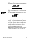
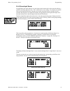
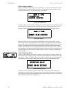
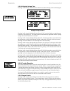
3.5.6 System Setup
System Setup allows the programmer to configure the following control panel features:
• Abort Type: Future Use
• Timers: This option allows the programmer to set the Soak 1, Soak 2, Waterflow and AC
Loss time delays.
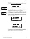
• Banner: This option allows the user to change the top two lines of the LCD display from the
factory default readout to a user defined readout when the control panel is in Normal
condition.
• Time-Date: This feature allows the programmer to set the time, display format (24 hr or 12
hr), date and daylight savings time feature into the FACP memory
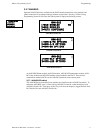
• Trouble Reminder: This feature, when enabled, provides an audible reminder that an alarm or
trouble still exists on the FACP after the control panel has been silenced. The control panel
piezo sounder will pulse once every 15 seconds during an alarm and every two minutes
during a trouble condition, after the Alarm Silence or Acknowledge key is pressed. The
piezo will continue to sound at these rates until the alarm or trouble condition is cleared. If
the Trouble Reminder feature is not
enabled and a trouble condition is not cleared within 24
hours, the panel will reactivate the trouble sounder an send an Abnormal 24 hour Test
message via the optional communicator.
• Charger Disable: This option allows the programmer to disable the onboard battery charger
in the event an external battery charger is being used.
ON-BOARD RELAYS
1=RELAY 1 ALARM
2=RELAY 2 TROUBLE
3=RELAY 3 SUPERVSRY
Relays Selection Screen
RELAY TYPE
1=ALARM
2=TROUBLE
3=SUPERVISORY
Relay Screen #1
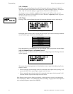
RELAY TYPE
1=FUTURE USE
2=DISCHARGE
3=AC LOSS
Relay Screen #2