


10 MRP-2001 & MRP-2001E PN 53040:A 4/16/2007
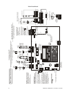
Main Circuit Board
Resettable Power - 24 VDC filtered,
power-limited, Class 2 (0.500 amps
maximum) to smoke detectors (IDC).
Supervise with a power supervision
relay EOLR-1
Nonresettable or Resettable Power
Jumper selectable by JP31, 24 VDC filtered,
power-limited, Class 2 (0.500 amps maximum)
. NonresettablePower suitable for
powering annunciators, Resettable
Power suitable for powering smoke detectors.
Supervise with a power supervision relay
EOLR-1
Configure TB9, Terminals 1 & 2
as Resettable or Nonresettable Power.
• Resettable Power - jumper JP31 pins 2 & 3.
• Nonresettable Power - jumper JP31
pins 1 & 2 (as shown).
Special Application Power
In this example NAC Output Circuits #1, #3 & #4, Style Y (Class B) (Supervised, Power Limited - Class 2)
NAC Output Circuit #2 (Releasing) is Style Y (Class B) (Supervised, NonPower-Limited, Class 1)
3.0 amps max. per circuit. (See Style Z illustrated near right edge of board).
4.7K , ½ watt End-of-Line Resistor PN 71252
Ω
Nonsupervised relay contacts
Contact Ratings:
2.0 amps @ 30 VDC (resistive)
0.5 amps @ 30 VAC (resistive)
Contacts shown below in normal
condition (AC power with no alarm,
trouble or supervisory activity).
A Fail Safe Trouble
relay switches to the
NC position during
trouble conditions and
under loss of all power.
Special Application
DC Power Outputs (24 VDC)
Nonsupervised, power-limited circuits (Class 2)
Supervise with a power supervision relay EOLR-1
Battery
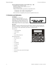
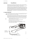
Basic System Connections
Output Circuits - TB5 & TB7
3 Programmable Relays
Alarm* Trouble*
Supervisory*
NO NC C
24 VDC, supervised,
nonpower-limited
26 Amp Hour maximum
NO NC CNO NC CNO NC C
(* )Factory default relay programming
Power Supply Connector J15
Output
Circuit #1
NAC
+
+
+
4
3
J12
BATTERY
- +
TB5
TB4
TB7
TB6
TB8
TB9
J2
J7
J15
J3
JP24
JP31
JP30
J5
J4
J6
TB3
GND PWR
ANN-BUS
A B
RST AUX
PWR
RST/NONRST
AUXPWR
OUT1 OUT2
OUT3 OUT4
4XTMF OPT BD
Cut this jumper to supervise
the 4XTMF module when
installed (see J4 & J5)
Cut this jumper to
enable Supervisory
relay when 4XTMF
module is installed
2
1
JP43
CAC5 Class A Converter Module
-
+
+
-
3
2
1
B
+
B
-
11
B
+
B
-
22
+
+
+
B
+
B
-
33
B
+
B
-
11
B
+
B
-
66
IDCs 1 through 6, Style B (Class B) (Supervised, Power Limited, Class 2)
(See Style D illustrated near right edge of board).
4.7K , ½ watt End-of-Line Resistor PN 71252
Ω
Input Initiating Device Circuit - TB4 & TB6
Remove jumper JP43
to disable Ground Fault
Detection circuit (only
with approval of AHJ).
+
+
+
TB5/
TB7
TB4/
TB6
OUT1/3 OUT2/4
A
+
A
-
11 2
A
+
A
-
11
OUT OUT
TB2
TB1
J2
CAC5
Class A Converter Module
Dummy load all unused circuits with
4.7K , ½ watt End-of-Line resistors
Ω
Style Z (Class A) NAC
Style D (Class A) IDC
+ - + -
+ - + -
+ - + - + - + - + -
Important!
Removing Ground Fault
DisableJumper JP43 voids UL/NFPA
Style/Class identifications for circuits.
Remove jumper JP43 only with the
approval of the AHJ
(Authority Having Jurisdiction).
- +
- +
+ -
FIRE ALARM
AC POWER
TROUBLE
1
4
7
*
2
3
1
5
6
89
0
#
ABC
DEF
GHI
JKL
PRS TUV
QZ_
_/.
CLEAR
ESC
MODE
ST
ENTER
ALARM
DRILL
RESET
Output
Circuit #2
Releasing
Releasing Circuit
(Supervised, Power-Limited, Class 2)
REL-4.7K
TB5
OUT1 OUT2
+ - + -
B
+
B
-
22
Unused
Output Circuit
4.7K dummy load
P/N 71245
Ω
B
+
5
B
-
5
Output
Circuit #3
NAC
Output
Circuit #4
Input IDC
Circuit #1
Input IDC
Supervisory
Circuit #5
Input IDC
Water flow
Circuit #6
smoke
detector
polarized
bell
polarized
horn
polarized
strobe
heat
detector
pull
station
Normally
Open
Tam pe r
or
Pressure
Switches
Normally
Open
Waterflow
Devices
or
Pressure
Switches
B
+
B
-
33
manual
release
A
+
A
-
11
A
+
A
-
11