


NFPA Standard-Specific Requirements Template 13: Single Hazard - Dual Zone
118 MRP-2001 & MRP-2001E PN 53040:A 4/16/2007
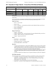
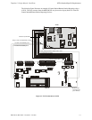
Notes:
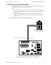
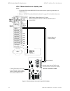
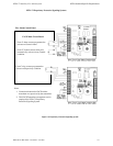
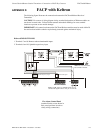
1. Reference the 411UD Manual for additional information
2. All connections between the control panel and the 411UD must be in conduit, less than 20 ft.
(610 cm) in length in the same room.
3. Any zone of the 411UD can be wired to function as alarm, trouble or supervisory; the 411UD
must be programmed accordingly. In this example, Channel/Zone 1 is wired to the control
panel’s alarm relay, Channel 2/Zone 2 is wired to the control panel’s trouble relay and
Channel 3/Zone 3 is wired to the control panel’s supervisory relay.
4. Nonresettable 24 VDC power is supplied to the 411UD via TB9 terminals configured for
nonresettable power on the FACP. Jumper J4 on the 411UD must be removed for 24 VDC
power.
5. End-of-Line resistors must terminate all 411UD circuits, including unused circuits.
6. Program the 411UD for slave operation.
7. The MRP-2001/E must be programmed for AC Loss Reporting Delay This prevents the
immediate transmission of a trouble on the loss of AC power.
8. A (-)VDC from the 411UD Trouble Contacts will activate the Trouble Input J6 on the FACP.
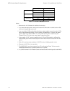
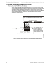
411UD FACP
Alarm TB2-1 TB8-1
TB2-2 TB8-3
Trouble TB2-3 TB8-4
TB2-4 TB8-6
Supervisory TB2-5 TB8-7
TB2-6 TB8-9
Table C.1 411-UD Connections to FACP