


Installation ANN-BUS Devices
30 MRP-2001 & MRP-2001E PN 53040:A 4/16/2007
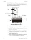
2.7 ANN-BUS Devices
WARNING! Disconnect all sources of power (AC and DC) before installing or removing any
modules or wiring.
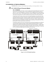
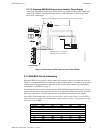
A variety of optional devices can be connected to the FACP ANN-BUS communication circuit.
Compatible devices include:
• ANN-80 LCD Annunciator
• ANN-S/PG Serial/Parallel Printer Interface Module
• ANN-I/O LED Driver Module
• ANN-LED Annunciator Module (annunciates alarms, troubles and supervisories)
• ANN-RLED Annunciator Module (annunciates alarms only)
• ANN-RLY Relay Module
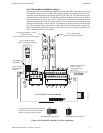
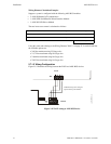
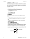
2.7.1 ANN-BUS Wiring
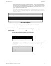
This section contains information on calculating ANN-BUS wire distances and the types of wiring
configurations (Class B).
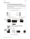
2.7.1.1 Calculating Wiring Distance for ANN-BUS Modules
The following instructions will guide the installer in determining the type of wire and the
maximum wiring distance that can be used with FACP ANN-BUS accessory modules.
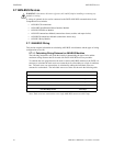
To calculate the wire gauge that must be used to connect ANN-BUS modules to the FACP, it is
necessary to calculate the total worst case current draw for all modules on a single 4-conductor
bus. The total worst case current draw is calculated by adding the individual worst case
currents for each module. The individual worst case values are shown in the following table:
Note: Total worst case current draw on a single ANN-BUS cannot exceed 0.5 amp.
Model Number Worst Case Current Draw
ANN-80 LCD Annunciator 0.040 amps
ANN-S/PG Serial/Parallel Printer Interface Module 0.040 amps
ANN-I/O LED Driver Module 0.200 amps
ANN-(R)LED Annunciator Module 0.068 amps
ANN-RLY Relay Module 0.075 amps