


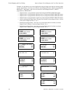
FACP Configuration Templates Template 8: Single Hazard - Cross-Zone With Manual Release
110 MRP-2001 & MRP-2001E PN 53040:A 4/16/2007
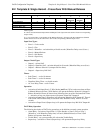
B.2 Template 8: Single Hazard - Cross-Zone With Manual Release
Table Legend:
X = direct correlation between Input Zone and Output Circuit (input zone activation will turn on corresponding
output circuit).
Cx = cross-zone where x is the number of the Release Solenoid. All inputs with the same Release Solenoid
number must be active at the same time to turn on the corresponding solenoid output circuit
Input Zone Types:
• Zone 1 = 2-wire smoke
• Zone 2 = Fire
• Zone 3 = Waterflow - activation delayed for 60 seconds (Waterflow Delay set to 60 secs.)
• Zone 4 = Manual Release
• Zone 5 = Pull Station
• Zone 6 = Supervisory
Output Circuit Types:
• Output 1 = Alarm NAC
• Output 2 = Waterflow NAC - activation delayed for 60 seconds (Waterflow Delay set to 60 sec)
• Output 3 = Release Solenoid 1 (unsupervised for shorts)
• Output 4 = Supervisory Bell NAC
Timers
• Soak Timer 1 - set for 10 minutes
• Soak Timer 2 - set for 10 minutes
• Waterflow Delay Timer - set for 60 seconds
• AC Loss Delay Timer - set for 2 hours
Operation
• Activation of both Input Zone 1 (2-Wire Smoke) and Zone 2 (Fire) at the same time, or Zone
4 (Manual Release) or Zone 5 (Pull Station) will operate the Release Solenoid 1 Output #3.
Release Solenoid will turn off water release following time-out of the 10 minute Soak Timer
1. Activation of any one of these zones will operate Alarm NAC Output #1
• Activation of Input Zone 3 (Waterflow) will operate the Waterflow NAC Output #2. There is
a 60 second FACP initiated delay in activation since Waterflow Delay Timer is set to 60
seconds
• Activation of Input Zone 6 (Supervisory) will operate the Supervisory Bell NAC Output #4
FACP Relay Operation
The following description of FACP relay operations are in addition to normal system operation.
• Alarm Relay - activation of Input Zone 1 (2-Wire Smoke) or Zone 2 (Fire) or Zone 3
(Waterflow - with Waterflow Delay time) or Zone 4 (Manual Release) or Zone 5 (Pull
Station) will operate Alarm Relay
• Trouble Relay - any system trouble will activate the Trouble Relay
• Supervisory - activation of Zone 6 (Supervisory) will operate the Supervisory Relay
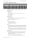
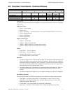
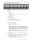
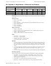
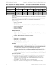
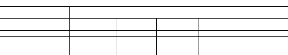
TEMPLATE 8: CROSS-ZONE WITH MANUAL RELEASE SWITCH
INPUT ZONES
123456
OUTPUT CIRCUITS 2-WIRE SMOKE FIRE WATERFLOW MANUAL
RELEASE
PULL
STATION
SUPV.
#1 ALARM NAC X X X X
#2 WATERFLOW NAC X
#3 RELEASE SOLENOID 1 C1 C1 X X
#4 SUPV. BELL NAC X