


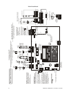
Backbox Mounting Installation
MRP-2001 & MRP-2001E PN 53040:A 4/16/2007 17
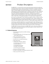
SECTION 2 Installation
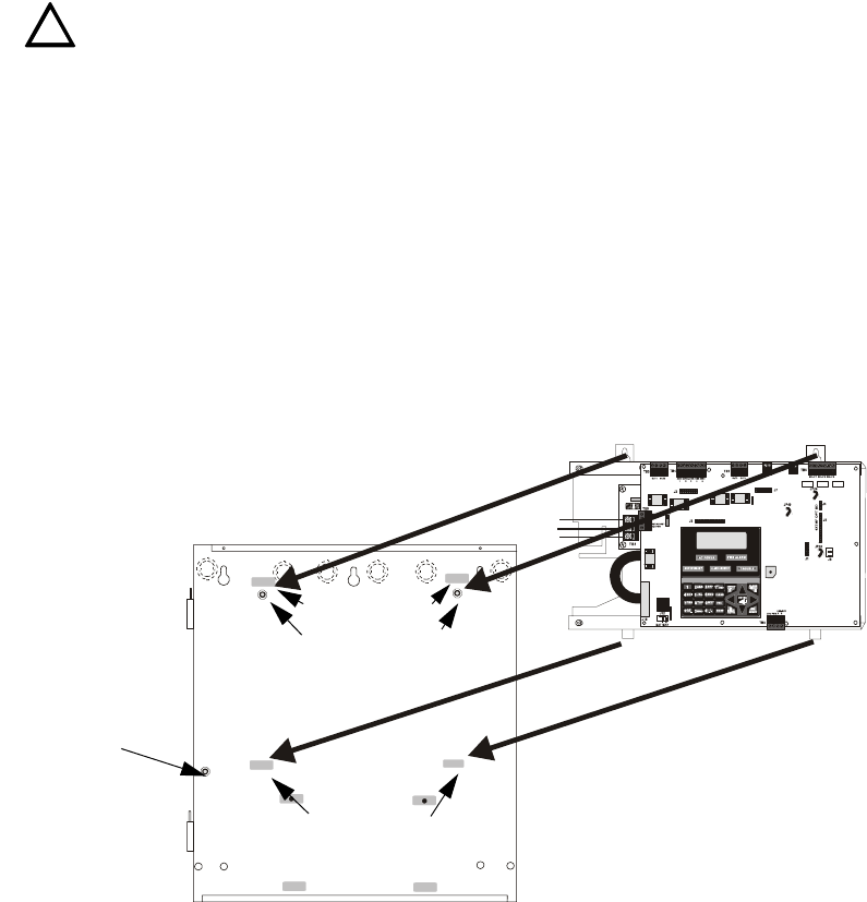
The cabinet can be surface mounted or semi-flush mounted. The door is removable during the
installation period by opening and lifting it off the hinges. The cabinet mounts using two key slots
at the top of the backbox and two additional securing holes located at the bottom.
Carefully unpack the system and check for shipping damage. Mount the cabinet in a clean, dry,
vibration-free area where extreme temperatures or levels of humidity are not encountered. The area
should be readily accessible with sufficient room to easily install and maintain the panel. Locate
the top of the cabinet approximately 5 feet (1.5 m) above the floor with the hinge mounting on the
left. Determine the number of conductors required for the devices to be installed. Sufficient
knockouts are provided for wiring convenience. Select the appropriate knockout(s) and pull the
conductors into the box. All wiring should be in accordance with the National and/or Local codes
for fire alarm systems.
2.1 Backbox Mounting
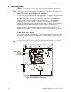
The circuit board contains static-sensitive components. Always ground yourself with a proper wrist
strap before handling any boards so that static charges are removed from the body. Use static
suppressive packaging to protect electronic assemblies.
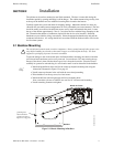
To prevent damage to the circuit board and to facilitate backbox mounting, the chassis with main
circuit board and transformer can be easily removed. Loosen the two 3/8” nuts securing the top
flanges of the chassis, then slide the chassis up to free it from the lower tabs. Place the chassis
assembly in a protective antistatic bag in a safe location until it can be reinstalled in the backbox.
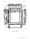
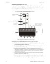
Mark and predrill hole in the wall for the center top keyhole mounting bolt using the
dimensions illustrated in Figure 2.2 on page 18
Install center top fastener in the wall with the screw head protruding
Place backbox over the top screw, level and secure
Mark and drill the left and right upper and lower mounting holes
Note: outer holes (closest to sidewall) are used for 16” on-center stud mounting
Install remaining fasteners and tighten
!
See Page
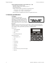
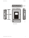
mounting studs
mounting slots
mounting tabs
mounting holes
grounding stud:
attach solid earth
ground wire (refer to
Figure 2.4 on page 20)
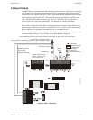
Board on Chassis
Backbox
Figure 2.1 Chassis Mounting in Backbox
5UDBRDINBOX.CDR
mounting slots