


Template 13: Single Hazard - Dual Zone FACP Configuration Templates
MRP-2001 & MRP-2001E PN 53040:A 4/16/2007 115
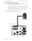
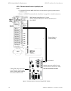
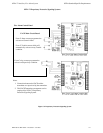
B.7 Template 13: Single Hazard - Dual Zone
Table Legend:
X = direct correlation between Input Zone and Output Circuit (input zone activation will turn on
corresponding output circuit).
Input Zone Types:
• Zone 1 = 2-wire smoke
• Zone 2 = Fire
• Zone 3 = Low Pressure
• Zone 4 = Waterflow - activation delayed for 10 seconds (Waterflow Delay set to 10 secs.)
• Zone 5 = Pull Station
• Zone 6 = Manual Release
Output Circuit Types:
• Output 1 = Alarm NAC
• Output 2 = Waterflow NAC - activation delayed for 10 seconds (Waterflow Delay set to 10 secs.)
• Output 3 = Release Solenoid 1 (unsupervised for shorts)
• Output 4 = Waterflow NAC - activation delayed for 10 seconds (Waterflow Delay set to 10 secs.)
Timers
• Soak Timer 1 - set for 10 minutes
• Soak Timer 2 - set for 10 minutes
• Waterflow Delay Timer - set for 10 seconds
• AC Loss Delay Timer - set for 2 hours
Operation
• Activation of Input Zone 1 (2-Wire Smoke) or Zone 2 (Fire) or Zone 5 (Pull Station) or
Zone 6 (Manual Release) will operate the Alarm NAC Output #1 and Release Solenoid 1
Output #3. Release Solenoid will turn off water release following time-out of the 10 minute
Soak Timer 1
• Activation of Input Zone 4 (Waterflow) will operate the Alarm NAC Output #1, Waterflow
NAC Output #2 and Waterflow NAC Output #4. There is a 10 second FACP initiated delay
in activation of these outputs since the Waterflow Delay Timer is set to 10 seconds
• Activation of Input Zone 3 (Low Pressure) will not operate any Output Circuits (see Relays)
FACP Relay Operation
The following description of FACP relay operations are in addition to normal system operation.
• Alarm Relay - activation of Input Zone 1 (2-Wire Smoke) or Zone 2 (Fire) or Zone 3
(Waterflow - with Waterflow Delay time) or Zone 4 (Manual Release) or Zone 5 (Pull
Station) will operate Alarm Relay
• Trouble Relay - any system trouble will activate the Trouble Relay
• Supervisory - activation of Zone 3 (Low Pressure) will operate the Supervisory Relay
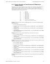
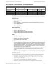
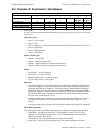
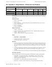
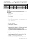
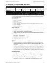
TEMPLATE 13: SINGLE HAZARD - DUAL ZONE
INPUT ZONES
123456
OUTPUT CIRCUITS 2-WIRE SMOKE FIRE LOW
PRESS.
WATERFLOW PULL
STATION
MANUAL
RELEASE
#1 ALARM NAC X X X X X
#2 WATERFLOW NAC X
#3 RELEASE SOLENOID 1 X X X X
#4 WATERFLOW NAC X