


Installation Installation of Optional Modules
28 MRP-2001 & MRP-2001E PN 53040:A 4/16/2007
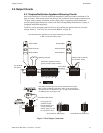
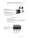
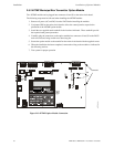
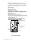
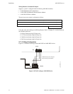
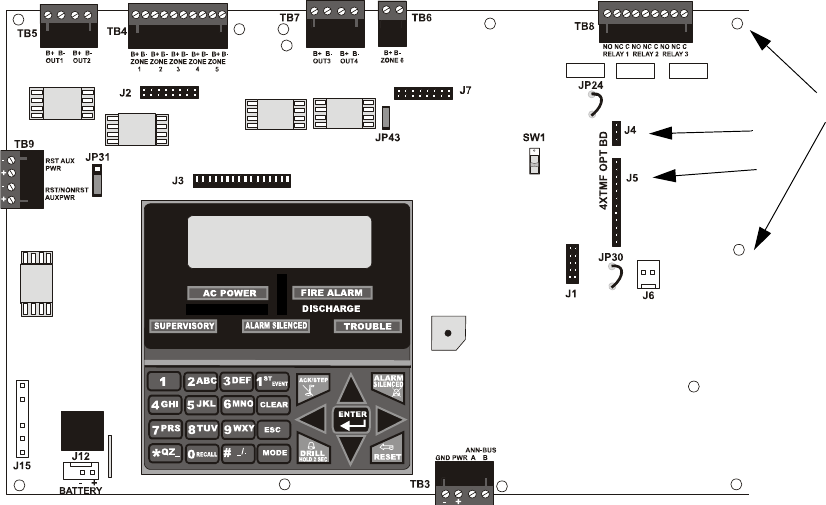
2.6.2 4XTMF Municipal Box Transmitter Option Module
The 4XTMF module can be plugged into connectors J4 and J5 on the main circuit board.
The following steps must be followed when installing the 4XTMF module:
1. Remove all power (AC and DC) from the FACP before installing the modules
2. Cut jumper JP30 on the main circuit board to allow the control panel to supervise the
placement of the 4XTMF option module
3. Install the two supplied metal standoffs in the locations indicated. These standoffs provide
the required earth ground protection
4. Carefully plug the connectors on the option module into connectors J4 and J5 on the FACP
main circuit board, being careful not to bend any pins
5. Secure the option module to the standoff on the main circuit board with the supplied screws
6. When the installation has been completed, connect the wiring to the modules as indicated in
the following sections
7. Test system for proper operation
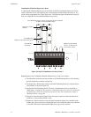
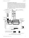
Figure 2.13 4XTMF Option Module Connection
J4
J5
Standoffs
rp2001bord.cdr