


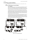
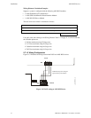
Installation ANN-BUS Devices
32 MRP-2001 & MRP-2001E PN 53040:A 4/16/2007
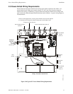
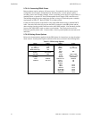
Wiring Distance Calculation Example:
Suppose a system is configured with the following ANN-BUS modules:
• 2 ANN-80 Remote LCD Annunciators
• 1 ANN-S/PG Serial/Parallel Printer Interface Module
• 1 ANN-I/O LED Driver Module
The total worst case current is calculated as follows:
Using this value and referring to the Wiring Distance Table 2.1 on page 31, it can be found that
the available options are:
463 feet maximum using 22 Gauge wire
1,172 feet maximum using 18 Gauge wire
1,866 feet maximum using 16 Gauge wire
2,953 feet maximum using 14 Gauge wire
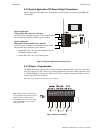
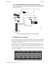
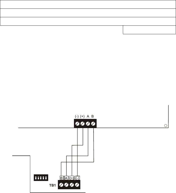
2.7.1.2 Wiring Configuration
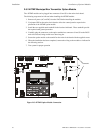
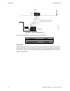
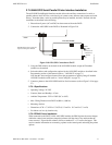
Figure 2.15 illustrates the wiring between the FACP and ANN-BUS devices.
ANN-80 Current Draw = 2 X 0.040 amps = 0.080 amps
ANN-S/PG Current Draw = 1 X.0.040 amps = 0.040 amps
ANN-I/O Current Draw = 1 X.0.200 amps = 0.200 amps
Total Worst Case Current Draw = 0.320 amps
Figure 2.15 FACP wiring to ANN-BUS Device
FACP
ANN-80
ANN-BUS and power wiring are
supervised and power-limited
TB3
aan80toRP2001.cdr