


128 MRP-2001 & MRP-2001E PN 53040:A 4/16/07
Index
Disable Release 46, 52
Disable/Enable 89
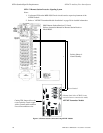
DP-51050LED Dress Panel 16
dress panel 12, 16
Drill 12, 14, 85
E
earth ground 20
edit
detector screens 51
Enable/Disable 82
zone 51
End-of-Line resistor
IDC 13, 21, 22
NAC 13, 23
Enter key 48
Erase History 78
exiting
programming 47, 48
Read Status 47, 48
F
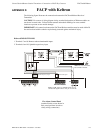
FACP configuration 50
fail-safe
trouble relay 24
features 11
Form-C
see also relay 11
freeze 21, 89
freeze signal
see also smoke detector monitoring 11
H
History 78, 97
erase 78
Maintenance Level 82
view events
78
history log 11
I
I3 detectors 21
IDC 11, 13, 21
alarm current 13
compatibility 21
End-of_Line resistor 22
End-of-Line resistor 13, 21
maximum loop resistance 13, 21
short circuit current 13
standby current 13
wiring 21
Indicator
AC Power 12, 15
Alarm Silence 12, 15
discharge 12, 15
Fire Alarm 12, 15
Supervisory 12, 15
System Trouble 15
Trouble 12
indicator
AC Power 86
Alarm Silenced 86
discharge 86
Fire Alarm 86
Supervisory 86
Trouble 86
Indicators 15
indicators 12,
14
Initiating Device Circuit 11, 13, 21
Class A 27
In-Line resistor
IDC combination circuit 22
input zone types 52
Input Zones 50, 93
installation 17
4XTM 29
class A converter module 26
option modules 26
transmitter module 28
J
J4 and J5
option module connectors 28
JP30 jumper
placement supervision 28
K
Key Panel 14
function keys 14
service/program keys 14
L
lamp test 14
LCD display 11, 14
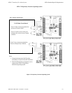
LED annunciator module 16
LED driver module 16, 39
connections 40
specifications 39
wiring LEDs 41
LED option module
LED zone assignments 75
M
Main 10
maintenance 21
piezo pulse rate 15
Maintenance Alert 90
Maintenance Program Level 2 47, 81
maintenance signal
see also smoke detector monitoring 11
Manual programming 46
Map 53
March Time 62
Master Program Level 1 47, 49
Mode key 48
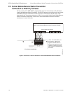
Mounting
main circuit board 17
mounting
cabinet 17
municipal box 29
municipal box transmitter
see also 4XTM 16