


Components Product Description
MRP-2001 & MRP-2001E PN 53040:A 4/16/2007 15
Local Piezo Sounder
A piezo sounder provides separate and distinct pulse rates for alarm, trouble and supervisory
conditions.
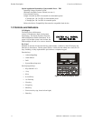
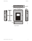
Indicators
Indicators are provided to annunciate the following conditions:
• Fire Alarm - red indicator
• Supervisory - yellow indicator
• AC Power - green indicator
• System Trouble - yellow indicator
• Alarm Silence - yellow indicator
• Discharge - red indicator
Local Piezo Sounder
A piezo sounder provides separate and distinct sounds for alarm, trouble, maintenance and
supervisory conditions as follows:
• Alarm - on steady
• Trouble - pulse 1 second on and 1 second off
• Maintenance - pulse ½ second on and ½ second off
• Supervisory - pulse ½ second on and ½ second off
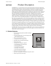
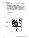
1.4 Components
Main Circuit Board
The main circuit board contains the system’s CPU and other primary components and wiring
interface connectors. Optional modules plug in and are mounted to the main circuit board.
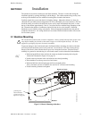
Power Supply
One FLPS-7 power supply is provided standard with each FACP, mounted to a chassis.
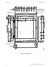
Cabinet
The backbox measures 16.65” (42.29 cm) x 19.0” (48.26 cm) x 5.207” (13.23 cm) and provides
space for two batteries (up to 18 Amp Hours). Also available is an optional dress panel (DP-51050
[red] and supplied standard with Canadian versions only, DP-51050LED for mounting ANN-LED
annunciator modules) which mounts inside the cabinet and trim-ring (TR-CE [red]).
Batteries
The cabinet provides space for two 18 Amp Hour batteries (larger batteries require use of a UL
listed battery box such as the BB-26 or BB-55). Batteries must be ordered separately.