


ANN-BUS Devices Installation
MRP-2001 & MRP-2001E PN 53040:A 4/16/2007 35
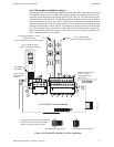
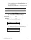
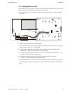
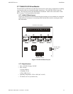
2.7.5.3 Wiring ANN-80 to FACP
The following steps can be used as a guide to wire the annunciator. Make certain all power has
been removed from the FACP prior to annunciator installation.
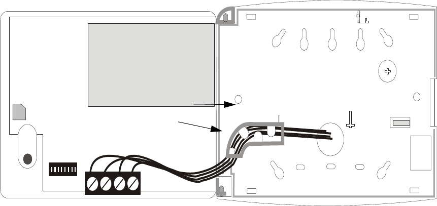
1. Route wires from hole in backplate, through wiring channel and then to ANN-80 terminal
block TB1
2. Remove appropriate amount of wire insulation
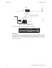
3. Connect the wiring from the FACP ANN-BUS to annunciator TB1 terminals 3 (A) & 4 (B).
Make certain to connect A to A and B to B
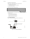
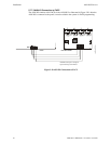
4. If appropriate, connect the wiring going to the next device on the ANN-BUS to TB1
terminals 3 & 4. Make certain to connect A to A and B to B
5. Connect the wiring from the 24 VDC power source to annunciator TB1 terminals 1 (-) & 2
(+). Make certain to observe proper polarity
6. If appropriate, connect the power wiring going to the next device to terminals
1 (-) & 2 (+). Make certain to observe proper polarity
7. After all connections are made, remove extra wire from inside of annunciator by dressing it
neatly through wire channel, with any excess wire pushed back through hole into electrical
box
wiring channel
wires
TB1