


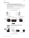
ANN-BUS Devices Installation
MRP-2001 & MRP-2001E PN 53040:A 4/16/2007 31
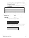
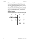
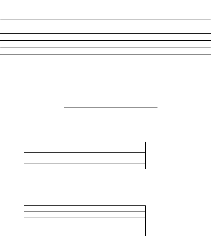
After calculating the total worst case current draw, Table 2.1 specifies the maximum distance
the modules can be located from the FACP on a single wire run. The table ensures 6.0 volts of
line drop maximum. In general, the wire length is limited by resistance, but for heavier wire
gauges, capacitance is the limiting factor.
These cases are marked in the chart with an asterisk (*). Maximum length can never be more
than 6,000 feet (1,800 m), regardless of gauge used. The formula used to generate this chart is
shown in the note below.
Note: The following formulas were used to generate the wire distance chart:
Exception: When using the ANN-RLY module, the installer must ensure that the maximum
24VDC power line drop does not exceed 0.3 volts. This results in the following wiring
limitations:
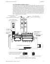
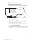
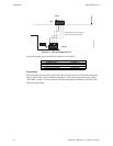
Wiring Distance: ANN-BUS Modules to FACP
Total Worst Case Current
Draw (amps)
22 Gauge 18 Gauge 16 Gauge 14 Gauge
0.100 1,852 ft. 4,688 ft. * 6,000 ft. *6,000 ft.
0.200 926 ft. 2,344 ft. 3,731 ft. 5,906 ft.
0.300 617 ft. 1,563 ft. 2,488 ft. 3,937 ft.
0.400 463 ft. 1,172 ft. 1,866 ft. 2,953 ft.
0.500 370 ft. 938 ft. 1,493 ft. 2,362 ft.
Table 2.1 Wiring Distances
Maximum Resistance (Ohms) = 6.0 Volts
Total Worst Case Current Draw (amps)
Maximum Wire Length (feet) = Maximum Resistance (Ohms) *500
(6,000 feet maximum) Rpu
where: Rpu = Ohms per 1,000 feet for various Wire Gauges (see table below)
Wire Gauge Ohms per 1,000 feet (Rpu)
22 16.2
18 6.4
16 4.02
14 2.54
Wire Gauge Maximum Wire Length
18 312 feet
16 497 feet
14 787 feet
12 1,250 feet