


Output Circuits Installation
MRP-2001 & MRP-2001E PN 53040:A 4/16/2007 23
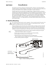
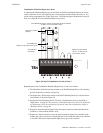
2.4 Output Circuits
2.4.1 Outputs/Notification Appliance/Releasing Circuits
Each of the four Style Y (Class B) Notification Appliance Circuits can output a maximum of 3.0
amps of current. Total current drawn from these as well as other DC power outputs cannot exceed
7.0 amps (refer to battery calculations section). Each circuit is supervised, power-limited and
provides special application power. Refer to the Device Compatibility Document for a listing of
compatible notification appliances.
The NACs can be converted to Style Z (Class A) by installing two optional Class A Converter
module. Refer to "CAC-5X Class A Converter Module" on page 26.
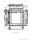
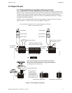
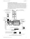
Figure 2.7 NAC/Output Connections
Class B Notification Appliance Circuits (supervised and power-limited)
4.7 KΩ, ½ watt resistor P/N:71252
Dummy load any unused
circuits (P/N: 71245)
Polarized Bell
Polarized Strobe
Polarized Horn
Polarized Horn
Polarized Bell
Notification Appliance Circuits
polarity shown in alarm condition
rp2001nac.cdr
Releasing Solenoid
Polarized Strobe
+ - + -
+ - + -
Note: Short Circuit Supervision must be enabled when using the
REL-4.7K for Canadian Applications. Refer to the section titled
"Release Circuit 1 or Release Circuit 2" on page 58 for information
on enabling short circuit supervision.
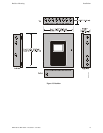
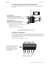
Ferrite Bead in open position
Ferrite Bead in closed position
Large gauge wire
should be looped
through bead at least
once as illustrated.
Smaller gauge wire can
be looped more often.
Ferrite Bead (P/N 29150)
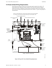
Ferrite Bead
P/N 29150
Ferrite Beads
P/N 29150