


Installation Input Circuits
22 MRP-2001 & MRP-2001E PN 53040:A 4/16/2007
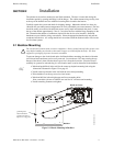
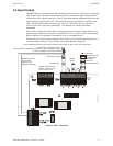
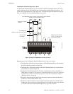
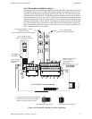
Combination Waterflow/Supervisory Zone
A combination Waterflow/Supervisory circuit allows an FACP to distinguish between an Alarm
switch (waterflow device) and a Supervisory switch (tamper) installed on the same circuit. Any
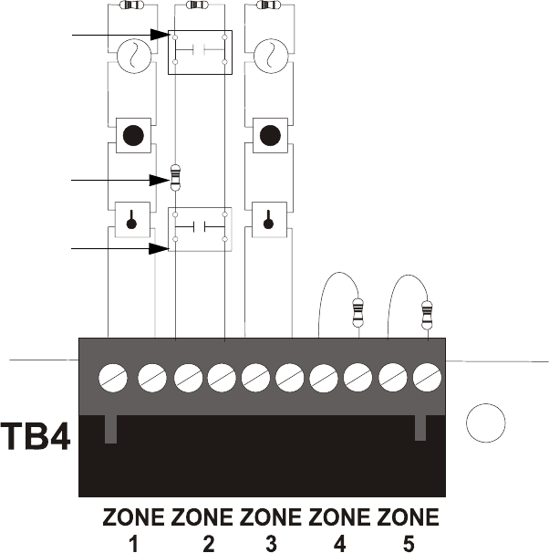
circuit can be programmed as a Combo Type zone. The following figure illustrates the wiring of
Zone 2 as a Style B (Class B) Waterflow/Supervisory circuit.
Requirements for the Combination Waterflow/Supervisory circuit are as follows:
The Waterflow Alarm Switch must connect to the FACP Initiating Device Circuit before
the In-Line Resistor as shown in Figure 2.6
The Supervisory Switch must connect to the FACP Initiating Device Circuit after the In-
Line Resistor as shown in Figure 2.6
Program the FACP Initiating Device Circuit as a Combination circuit as described in
"Input Zones" on page 50. Note that since a Waterflow Supervisory Switch is included in
a Combination circuit, the waterflow delay must be taken into consideration. Refer to
"Waterflow Delay" on page 66.
Waterflow Alarm Switch activation causes the panel to latch into alarm until the alarm
condition is cleared and the FACP is reset
Supervisory Switch activation causes the panel to latch the supervisory condition if the
Combo type code is selected or track (the panel will clear when the supervisory condition
is cleared) if the Combo Autoresettable Supervisory type code is selected
Class B Initiating Device Circuits (supervised and power-limited)
4.7 KΩ, ½ watt resistor P/N:71252
In-Line-Resistor
1.2 KΩ, ½ watt resistor P/N: 75579
Alarm Switch
(waterflow)
Dummy load all unused
circuits - 4.7 KΩ, ½ watt
resistor (P/N: 71245)
Figure 2.6 Style B Combination Circuit on Zone 2
Supervisory Switch
(tamper)
ms10udcomboIDC.cdr