


Input Circuits Installation
MRP-2001 & MRP-2001E PN 53040:A 4/16/2007 21
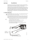
2.3 Input Circuits
The MRP-2001 has six programmable IDCs (Initiating Device Circuits). Each circuit is compatible
with System Sensor’s i
3
smoke detectors which generate a maintenance signal when the detector
becomes dirty and a separate supervisory ‘freeze’ signal when ambient temperature falls below the
detector rating of approximately 45
o
F. The maximum loop resistance limit for each IDC is 100
ohms. The maximum number of detectors per zone is 25. The field wiring for each zone is
supervised for opens, shorts and ground faults. All conditions are visually and audibly
annunciated.
Each circuit is configured for Style B (Class B) operation and will accept i
3
smoke detectors, any
normally-open contact devices as well as conventional 2-wire or 4-wire, 24 VDC smoke detectors.
Refer to the Device Compatibility Document for a list of compatible devices.
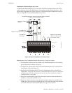
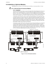
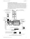
Initiating Device Circuits can be converted to Style D (Class A) by installing the optional Class A
Converter module. Refer to "CAC-5X Class A Converter Module" on page 26.
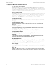
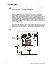
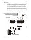
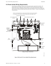
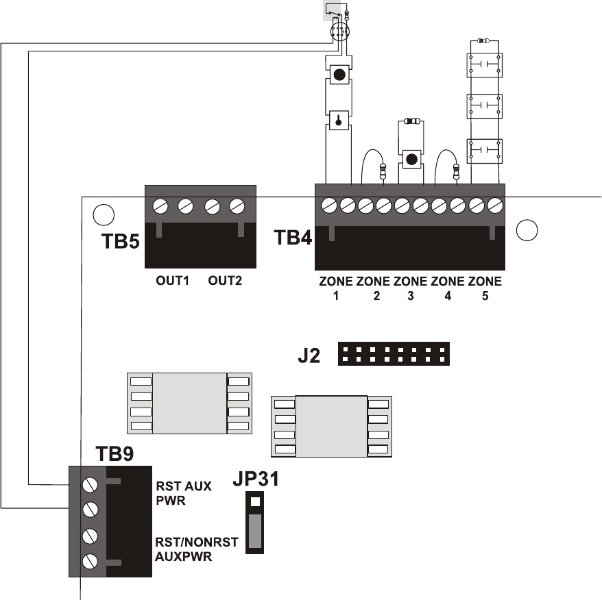
Figure 2.5 IDC Connections
Class B Initiating Device Circuits (supervised and power-limited) 4.7 KΩ, ½ watt resistor P/N:71252
manual pull stations
heat detectors
Dummy load all unused
circuits - 4.7 K
Ω, ½ watt
resistor (P/N: 71245)
mrp-2001idc.cdr
UL listed Power Supervision Relay
(refer to Device Compatibility Document for list of compatible relays)
Resettable 24 VDC
4-wire smoke
detector power
(500 mA maximum)
UL listed compatible 4-wire smoke detector
manual
release
Input IDC
Waterflow Circuit
Normally Open
Waterflow
Devices or
Pressure Switches