


ANN-BUS Devices Installation
MRP-2001 & MRP-2001E PN 53040:A 4/16/2007 33
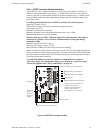
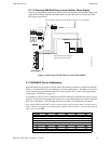
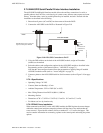
2.7.1.3 Powering ANN-BUS Devices from Auxiliary Power Supply
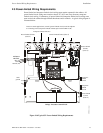
Figure 2.16 illustrates the powering of ANN-BUS devices from an auxiliary power supply such
as the FCPS-24FS6/8, when the maximum number of ANN-BUS devices exceeds the ANN-
BUS power requirements.
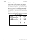
2.7.2 ANN-BUS Device Addressing
Each ANN-BUS device requires a unique address (ID Number) in order to communicate with the
FACP. A 5-position DIP switch on each device is used to set this address. The address set for these
devices must also be programmed at the FACP for the specific device (refer to the programming
section titled "ANN-BUS" on page 71).
A maximum of 8 devices can be connected to the FACP ANN-BUS communication circuit. Device
addresses do not need to be sequential and can be set to any number between 01 and 08. Note that
00 is not a valid address. The following table shows the DIP switch setting for each address.
Note: address (ID Number) DIP switches on some devices may have more than 5 switch positions.
Unless otherwise specified in the documentation supplied with each device, switch positions 6 and
above must be set to OFF.
Address Switch 5 Switch 4 Switch 3 Switch 2 Switch 1
not valid OFF OFF OFF OFF OFF
01 OFF OFF OFF OFF ON
02 OFF OFF OFF ON OFF
03 OFF OFF OFF ON ON
04 OFF OFF ON OFF OFF
05 OFF OFF ON OFF ON
06 OFF OFF ON ON OFF
07 OFF OFF ON ON ON
08 OFF ON OFF OFF OFF
Figure 2.16 Powering ANN-BUS Devices from FCPS-24FS6/8
ANN-80
FACP
FCPS-24FS6/8
+24 VDC
-24 VDC
ANN-BUS
Cut Ground Fault Detection jumper JP1 (FACP monitors for ground faults)
ANN-BUS and power wiring are
supervised and power-limited
TB3
ann80toFCPSrp2001.cdr