


Product Description Controls and Indicators
14 MRP-2001 & MRP-2001E PN 53040:A 4/16/2007
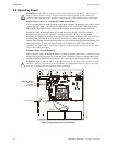
Special Application Resettable or Nonresettable Power - TB9
Operating Voltage: Nominal 24 VDC
Maximum Available Current: 500 mA (see note 1)
Power-limited Circuitry
Jumper selectable by JP31 for resettable or nonresettable power:
Jumper pins 1 & 2 on JP31 for nonresettable power
Jumper pins 2 & 3 on JP31 for resettable power
Refer to the Device Compatibility Document for compatible listed devices
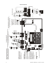
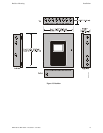
1.3 Controls and Indicators
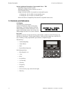
LCD Display
The FACP uses an 80-character
(4 lines X 20 characters) high viewing angle
LCD display. The display includes a long life
LED backlight that remains illuminated. If AC
power is lost and the system is not in alarm, the
LED backlight will turn off to conserve batteries.
Key Panel
Mounted on the main circuit board, the key panel includes a window for the LCD display and
indicators as listed above. The key panel, which is visible with the cabinet door closed, has 25
keys, including a 16 key alpha-numeric pad similar to a telephone keypad.
Function keys:
• Acknowledge/Step
• Alarm Silence
• Drill
• System Reset (lamp test)
Service/program keys:
• Keys labeled 1 to 9
• * key
• # key
• 0 (recall) key
• 1st Event key
• Clear key
• Escape key
• Mode key
• Four cursor keys (up, down, left and right)
• Enter key
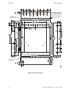
SYSTEM ALL NORMAL
10:00A 012106
Figure 1.1 Membrane/Display Panel
MRP2001kypd.cdr