


Table of Contents
4
MRP-2001 & MRP-2001E P/N: 53040:A 4/16/07
SECTION 1: Product Description .........................................................................................................................11
1.1: Product Features..........................................................................................................................................11
1.2: Specifications ..............................................................................................................................................13
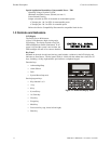
1.3: Controls and Indicators................................................................................................................................14
1.4: Components.................................................................................................................................................15
1.5: Optional Modules and Accessories .............................................................................................................16
SECTION 2: Installation ........................................................................................................................................17
2.1: Backbox Mounting......................................................................................................................................17
2.2: Operating Power..........................................................................................................................................20
2.3: Input Circuits...............................................................................................................................................21
2.4: Output Circuits ............................................................................................................................................23
2.4.1: Outputs/Notification Appliance/Releasing Circuits..........................................................................23
2.4.2: Special Application DC Power Output Connections ........................................................................24
2.4.3: Relays - Programmable.....................................................................................................................24
2.5: Power-limited Wiring Requirements...........................................................................................................25
2.6: Installation of Optional Modules.................................................................................................................26
2.6.1: CAC-5X Class A Converter Module ................................................................................................26
2.6.1.1 Installation ...............................................................................................................................26
2.6.1.2 Wiring NACs and IDCs for Class A .......................................................................................27
2.6.2: 4XTMF Municipal Box Transmitter Option Module........................................................................28
2.6.2.1 4XTMF Transmitter Module Installation ...............................................................................29
2.7: ANN-BUS Devices .....................................................................................................................................30
2.7.1: ANN-BUS Wiring.............................................................................................................................30
2.7.1.1 Calculating Wiring Distance for ANN-BUS Modules ............................................................30
2.7.1.2 Wiring Configuration ..............................................................................................................32
2.7.1.3 Powering ANN-BUS Devices from Auxiliary Power Supply ................................................33
2.7.2: ANN-BUS Device Addressing..........................................................................................................33
2.7.3: ANN-80 Remote LCD Annunciator .................................................................................................34
2.7.4: Specifications....................................................................................................................................34
2.7.5: Installation.........................................................................................................................................34
2.7.5.1 Mounting .................................................................................................................................34
2.7.5.2 Opening/Closing Annunciator ................................................................................................34
2.7.5.3 Wiring ANN-80 to FACP .......................................................................................................35
2.7.6: ANN-S/PG Serial/Parallel Printer Interface Installation...................................................................37
2.7.6.1 Specifications ..........................................................................................................................37
2.7.6.2 PRN-6 Printer Installation .......................................................................................................37
2.7.6.2.1 Connecting PRN-6 Printer ...................................................................................................38
2.7.6.2.2 Setting Printer Options .........................................................................................................38
2.7.7: ANN-I/O LED Driver Module..........................................................................................................39
2.7.7.1 ANN-I/O Board Layout ..........................................................................................................39
2.7.7.2 Specifications ..........................................................................................................................39
2.7.7.3 ANN-I/O Connection to FACP ...............................................................................................40
2.7.7.4 ANN-I/O Module LED Wiring ...............................................................................................41
2.7.8: ANN-LED Annunciator Module.......................................................................................................41
2.7.8.1 ANN-LED Board Layout ........................................................................................................42
2.7.8.2 Specifications ..........................................................................................................................42
2.7.8.3 Mounting/Installation ..............................................................................................................42
2.7.8.4 ANN-LED Connection to FACP ............................................................................................43
2.7.9: ANN-RLY Relay Module..................................................................................................................44
2.7.9.1 ANN-RLY Board Layout ........................................................................................................44
2.7.9.2 Specifications ..........................................................................................................................44
2.7.9.3 Mounting/Installation ..............................................................................................................44
2.7.9.4 ANN-RLY Connection to FACP ............................................................................................45
SECTION 3: Programming ..................................................................................................................................46
3.1: User Programming.......................................................................................................................................46
Table of Contents