


Installation of Optional Modules Installation
MRP-2001 & MRP-2001E PN 53040:A 4/16/2007 27
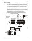
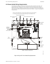
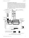
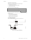
2.6.1.2 Wiring NACs and IDCs for Class A
Wire the Style Z (Class A) Notification Appliance Circuits using TB5 of the FACP main circuit
board and TB2 of the CAC-5X module. Wire the Style D (Class A) Initiating Device Circuits
using TB4 of the FACP main circuit board and TB1 of the CAC-5X. Note that the wiring will
be identical when using TB7 NAC and TB6 IDC of the FACP. Make certain to observe polarity
when connecting the devices to the circuits. The B+ and A+ terminals must comprise the feed
and return for the positive side of a device and the B- and A- terminals must comprise the feed
and return for the negative side of a device. To configure any of the zones for Class B when the
CAC-5X is installed, simply wire to the B+ and B- input on the FACP terminal(s) and install the
End-of-Line Resistor after the last device on the circuit. Do not wire to the corresponding A+
and A- terminals on the CAC-5X module.
Figure 2.12 Wiring NACs and IDCs for Class A Operation
CAC-5X Class A Converter Module
FACP Main
Circuit Board
Class B (Style B) IDC - 4.7 KΩ
½ watt ELR resistor
P/N:71252 (supervised and power-limited)
Dummy load all unused
circuits - 4.7 K
Ω
½ watt ELR resistor
(P/N: 71245)
Polarized
Bell
Circuit polarities
shown in alarm
condition
Class A (Style Z) NAC
(supervised and power-limited)
Class A (Style D) IDC
(supervised and power-limited)
Polarized
Strobe
Polarized
Horn
Smoke
Smoke
Pull Station
Pull Station
Heat
Heat
ms10udclassa.cdr
B+ B- B+ B-
A+ A-
A+ A-
A+ A- A+ A- A+ A- A+ A- A+ A-
B+ B- B+ B- B+ B- B+ B- B+ B-
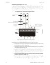
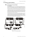
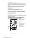
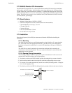
Ferrite Bead
P/N 29150
Large gauge wire should be looped through
bead at least once as illustrated. Smaller
gauge wire can be looped more often.
Ferrite Bead in open position
Ferrite Bead in closed position
2550ferr.cdr