More information online at bannerengineering.com
299
MEASUREMENT & INSPECTION
TEMPERATURE
ULTRASONIC
LIGHT
GAUGING
RADAR
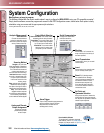
MEASURING LIGHT
SCREENS
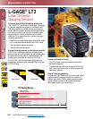
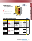
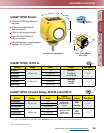
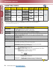
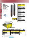
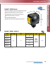
A-GAGE
®
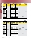
MINI-ARRAY
®
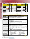
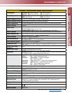
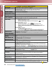
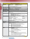
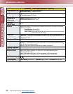
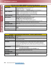
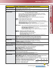
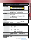
Controller Specifications
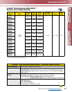
Power Requirements
16 to 30V dc
@
1.25 amps max. (see current requirements for sensors); controller alone,
(without sensors connected) requires 0.1 amp.
Inputs
Sensor input (5 connections): Emitter and receiver wire in parallel to ve terminals
Trigger (Gate) input: Optically isolated, requires 10 to 30V dc (7.5K input impedance) for gate signal
Discrete Outputs
MAC-1: Output 1 (OUT 1) - Reed relay contact rated 125V ac/dc max.,
10 VA max. resistive load (non-inductive).
Output 2 (ALARM) - Open collector NPN transistor rated 30V dc max., 150 mA max,
short-circuit protected; may be congured as a second data analysis output, a system
alarm output, or a scan trigger output for a parallel array
OFF-state leakage current: less than 10 µA @ 30V dc
ON-state saturation voltage: less than 1V @ 10 mA; less than 1.5V @ 150 mA
MACN-1: (2) Open collector NPN transistor outputs
MACP-1: (2) Open collector PNP transistor outputs;
transistor rated 30V dc max. 150 mA max, short circuit protected; may be congured as a
second data analysis output, a system alarm output, or a scan trigger output for a parallel array
OFF-state leakage current: less than 10 µA @ 30V dc
ON-state saturation voltage: less than 1V @ 10 mA; less than 1.5 V @ 150 mA
MACV-1/MACI-1: Alarm - Open collector NPN transistor rated 30V dc max. 150 mA max, short circuit
protected; may be congured as a data analysis output, a system alarm output, or a
scan trigger output for a parallel array
OFF-state leakage current: less than 10 µA @ 30V dc
ON-state saturation voltage: less than 1V @ 10 mA; less than 1.5 V @ 150 mA
MAC16P-1: Sixteen open collector PNP transistor outputs
MAC16N-1: Sixteen open collector NPN transistor outputs
30V dc max, 150 mA max., short circuit protected
OFF-state leakage current: less than 10 µA
ON-state saturation voltage: less than 1V @ 10 mA; less than 1.9V @ 150 mA
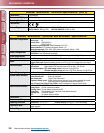
Serial Data Outputs
RS-232, ASCII or binary data format
Baud Rate: 9600, 19.2K, or 38.4K, 8 data bits, 1 start bit, 1 stop bit, even parity
Clear data may be suppressed Header string may be suppressed in binary format
MAC-1: Up to 15 controllers may be given unique address for RS-485 party line
Analog Outputs
MACV-1: 0-10 Volts sourcing adjustable Null and Span (20 mA current limit)
MACI-1: 4-20 mA current sinking adjustable Null and Span (16 to 30V input)
Resolution: Span/(Number of sensor channels) Linearity: 0.1% of Full Scale
Temperature variation: 0.01% of Full Scale/° C
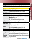
Controller Programming
All models: Via RS-232 PC-compatible computer running Windows
®
95, 98, NT, ME, XP or 2000
operating system and using Banner supplied software
Sensor Scan Time
All models: 55 microseconds per beam plus processing time.
The processing time is dependent on the scan analysis and the number of active outputs.
This timing assumes a straight scan, continuous, and TBB mode
MAC-1, MACN-1 & MACP-1: 1 millisecond processing time
MACV-1 & MACI-1: 1.5 milliseconds processing time
MAC16N-1 & MAC16P-1: 2.3 to 7 milliseconds processing time
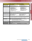
System Response Time
Outputs are not active for 5 seconds after system power up. Maximum response time for
the system is two sensor scan cycles.
A scan cycle includes a sensor scan plus any serial data transmission.
Serial transmission (if activated) follows every sensor scan.
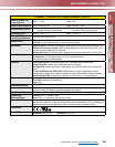
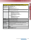
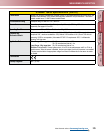
Status Indicators
The following status LEDs are located on the top surface of the module:
MACV-1 & MACI-1: V OUT (Red) - (also called I OUT) Indicates that the analog outputs are active
MAC-1, MACN-1 & MACP-1: OUT 1 (Red) - Indicates that output 1 is energized
MAC16N-1 & MAC16P-1: OUT (Red) - Indicates that at least one output is active
ALARM (Red) - Indicates that Output 2 is active/MAC16N-1 & MAC16P-1: Indicates output 16 is active
GATE (Red) - Indicates voltage is applied to Trigger (Gate) input
ALIGN (Green) - Indicates sensor aligned (excess gain > 1x)
DIAG1 (Green) - Indicates power is applied to the module*
DIAG2 (Red) - Indicates receiver failure
DIAG3 (Red) - Indicates emitter failure
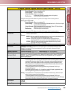
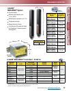
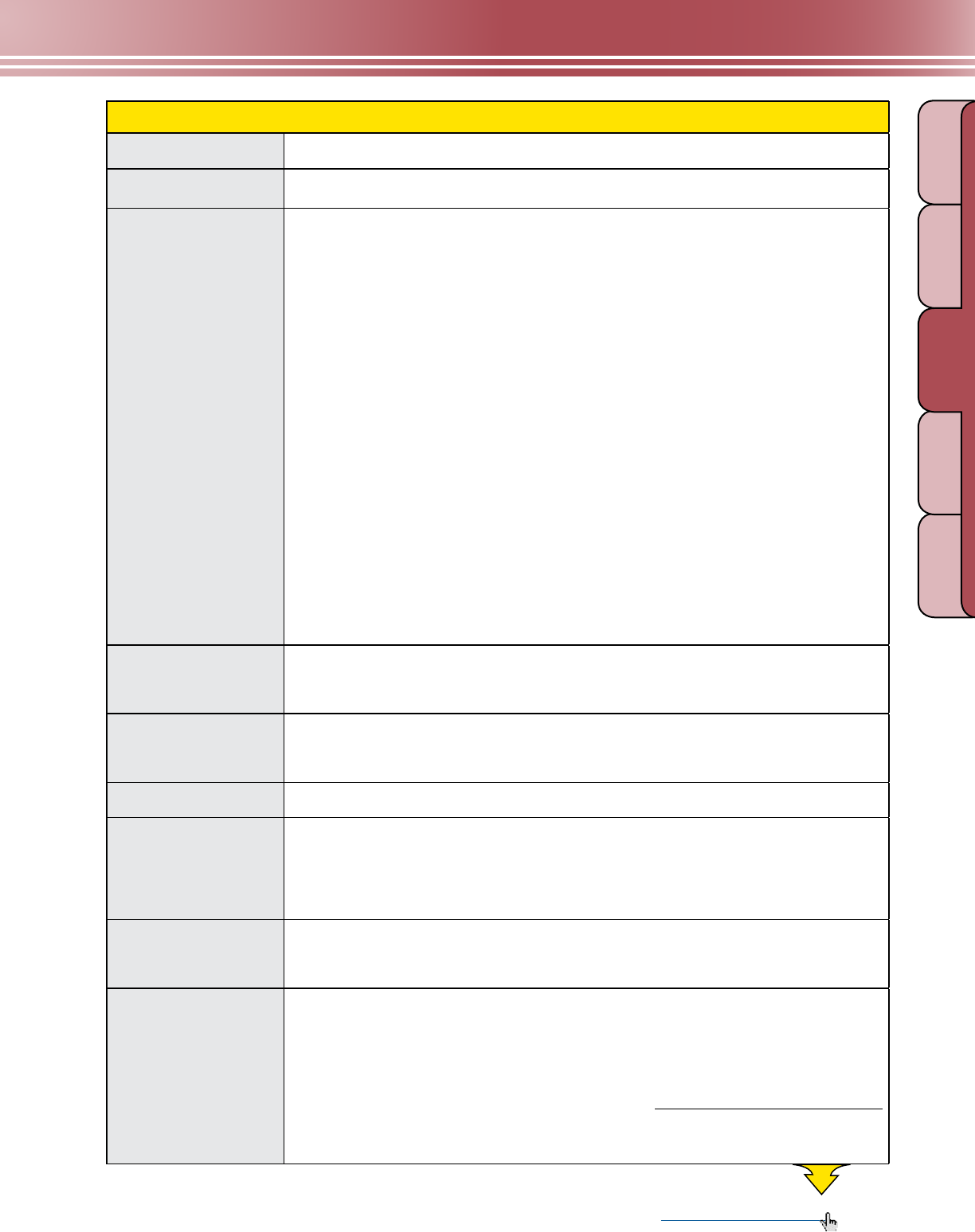
Condition
DIAG1
(Green)
DIAG2
(Red)
DIAG3
(Red)
Normal condition on off off
Receiver error on on off
Emitter error on off on
}
More on
next page