More information online at bannerengineering.com
283
MEASUREMENT & INSPECTION
MEASURING LIGHT
SCREENS
TEMPERATURE
LIGHT
GAUGING
RADAR
ULTRASONIC
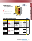
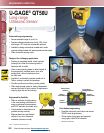
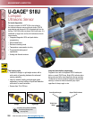
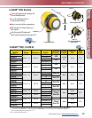
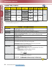
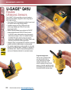
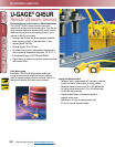
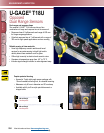
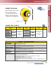
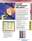
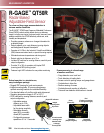
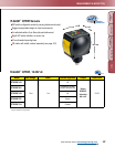
U-GAGE
®
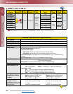
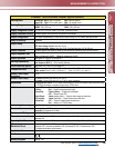
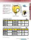
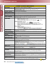
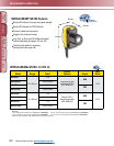
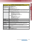
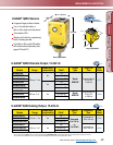
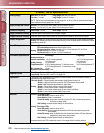
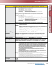
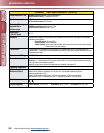
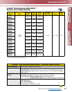
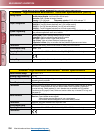
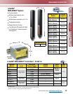
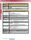
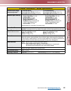
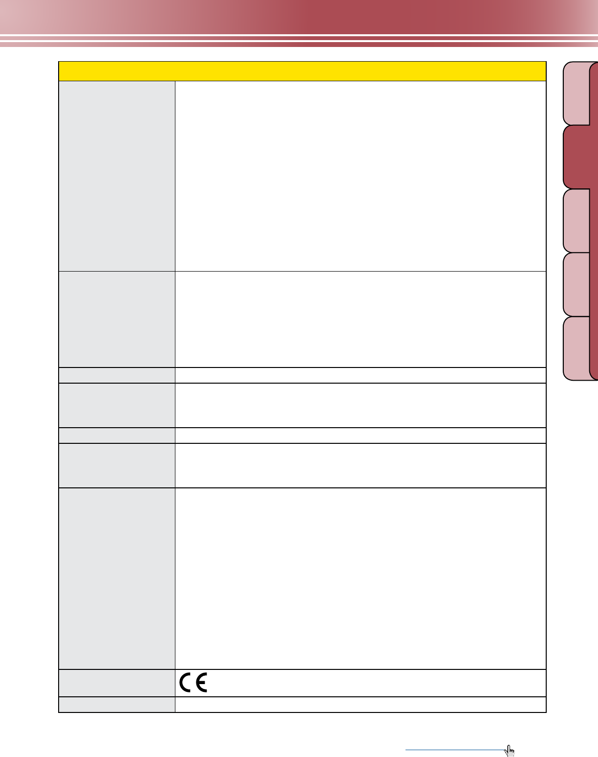
Q45UR Remote Sensors Specifications
Indicators
Discrete: Three status LEDs:
Green ON steady: Power to controller is ON
Green flashing: Output is overloaded
Yellow ON steady: Output are conducting
(Yellow also indicates programming status during setup)
Red flashing: Relative strength of received echo
5-segment moving dot LED indicates the position of the target within the sensing window
Analog: Three status LEDs:
Green ON steady: Power to controller is ON
Green flashing: Current output fault detected (indicates that the 4 to 20 mA current path
to ground has been opened)
Yellow ON steady: Target is sensed within the window limits (Yellow LED also indicates
programming status during setup mode)
Red flashing: Relative strength of received echo
5-segment moving dot LED indicates the position of the target within the sensing window
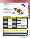
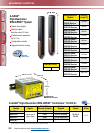
Construction
Controller: Molded thermoplastic polyester housing, o-ring sealed transparent acrylic top cover, and
stainless steel hardware
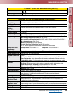
Sensors:
M18C2.0: Stainless steel M18 threaded barrel housing and jam nuts, polyetherimide front
cover, ceramic transducer, polyurethane rear cover
S18C2.0: Thermoplastic polyester S18 threaded barrel housing and jam nuts,
polyetherimide front cover, ceramic transducer, polyurethane rear cover
Q13C2.0: Molded 30% glass reinforced thermoplastic polyester housing, ceramic
transducer, fully epoxy-encapsulated
Environmental Rating
Controller: IEC IP67; NEMA 6P Sensor: IEC IP65; NEMA 4
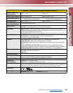
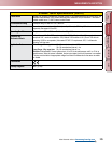
Connections
Controller: 2 m or 9 m attached cable, or 5-pin Mini-style or Euro-style quick-disconnect tting.
See pages 415 and 421.
Sensor: 2 m attached PVC cable terminated with 4-pin Euro-style quick-disconnect tting for
connection to controller.
Operating Conditions
Controller and sensor: -25° to +70° C Relative humidity: 85% (non-condensing)
Vibration and
Mechanical Shock
All models meet Mil. Std. 202F requirements. Method 201A Vibration: 10 to 60Hz max., double
amplitude 0.06” (maximum acceleration 10G). Method 213B conditions H & I (Shock: 75G with unit
operating; 100G for non-operation). Also meets IEC 947-5-2 requirements: 30G, 11 milliseconds
duration, half sine wave.
Application Notes
Discrete: The TEACH-mode function of the controller is used to set the sensing distance set point.
The sensing window size is set using DIP switches #2 and #3. The sensing distance set point is
centered within the sensing widow. The size of the sensing window may be adjusted at any
time, with or without power applied, and without re-teaching the sensing distance set point.
The controller has non-volatile memory which remembers the last sensing distance set point
setting if power is removed and later reapplied.
The sensing distance set point may be programmed using the Remote TEACH input
(see hookup diagrams).
Acceptable target angle is within ±5° of normal for a smooth, at target; target rotation does
affect the apparent target location with respect to the sensor.
Analog: The controller has non-volatile memory which remembers the last sensing distance set point
setting if power is removed and later reapplied.
The sensing distance set point may be programmed using the Remote TEACH input
(see hookup diagrams). Acceptable target angle is within ±5° of normal for a smooth, at target;
target rotation does affect the apparent target location with respect to the sensor.
Certifications
Hookup Diagrams
MI17 (p. 536)
(cont’d)