264 More information online at bannerengineering.com
COLOR &
lUMINESCENCE
PICK-TO-LIGHT
SLOT & LABEL
MEASUREMENT & INSPECTION
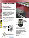
MEASURING LIGHT
SCREENS
TEMPERATURE
LIGHT
GAUGING
RADAR
ULTRASONIC
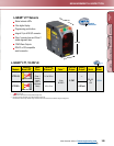
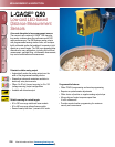
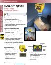
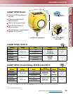
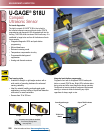
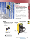
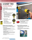
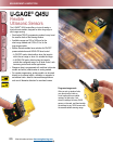
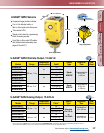
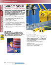
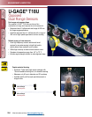
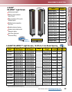
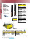
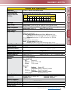
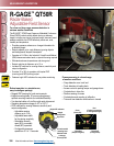
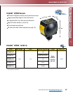
U-GAGE
®
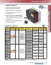
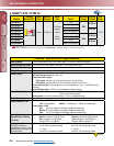
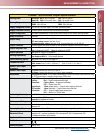
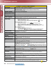
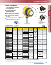
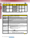
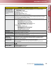
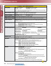
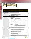
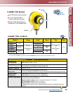
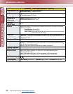
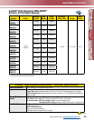
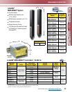
QT50U DC Specifications
Effective Beam
See charts EBPC-1, EBPC-2 and EBPC-3 on page 513.
Supply Voltage and Current
Analog models: 10 - 30V dc (10% max. ripple); 100 mA max
@
10V, 40 mA max. @ 30V (exclusive of load)
Dual-discrete models: 10 to 30V dc (10% max. ripple); 100 mA max.
@
10V,
40 mA
@
30V (exclusive of load)
Ultrasonic Frequency
75 kHz burst, rep. rate 96 milliseconds
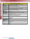
Supply Protection Circuitry
Protected against reverse polarity and transient overvoltages
Output Protection
Protected against short circuit conditions
Delay at Power-up
1.5 seconds
Output Configuration
Analog models: Voltage sourcing: 0 to 10V dc Current sourcing: 4 to 20 mA
Dual-discrete models: Dual PNP or NPN, selectable using DIP switch
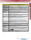
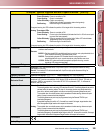
Output Ratings
Analog Voltage Output: 0 to 10V dc
Minimum load resistance = 500 Ω
Minimum required supply voltage for full 0-10V output span = (
1000
+ 13)V dc
RLOAD
Analog Current Output: 4 to 20 mA
Maximum load resistance = 1 kΩ or (
V supply - 5
) Ω, whichever is lower
0.02
Minimum required supply voltage for full 4-20 mA output span = 10V dc or
[(RLoad x 0.02)+5]V dc, whichever is greater. 4-20 mA output calibrated at 25° C with
250 Ω load.
Discrete Output: 150 mA max.
OFF-State leakage current: less than 5 µA
Output saturation: NPN: less than 200 mV @ 10 mA; less than 650 mV @ 150 mA
PNP: less than 1.2V @ 10 mA; less than 1.65V @ 150 mA
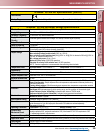
Temperature Effect
Uncompensated: 0.2% of distance/° C
Compensated: 0.02% of distance/° C
Linearity (Analog Models)
+/- 0.2% of span from 200 to 8000 mm; +/- 0.1% of span from 500 to 8000 mm (1 mm minimum)
Resolution/Repeatability
1.0 mm
Hysteresis
5 mm
Output Response Time
Analog models: 100 to 2300 milliseconds
Dual-discrete models: 100 to 1600 milliseconds
Minimum Window Size
20 mm
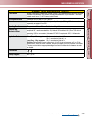
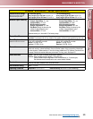
Adjustments
Sensing window limits: TEACH-Mode programming of near and far window limits may be set using
the push buttons or remotely using TEACH input.
Indicators
Green Power ON LED: Indicates power is ON
Red Signal LED: Indicates target is within sensing range, and the condition of the received signal.
Teach/Output indicator (bicolor Yellow/Red):
Yellow–Target is within taught limits Yellow OFF (Discrete)–Target is outside taught window limits
Red–Sensor is in TEACH mode Yellow Flashing (Analog)–Target is outside taught window limits
Remote TEACH
See data sheet p/n 70137 (Analog) and p/n 110112 (Discrete)
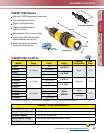
Construction
Transducer: Ceramic/Epoxy composite Housing: ABS/Polycarbonate
Membrane Switch: Polyester Lightpipes: Acrylic
Environmental Rating
Leakproof design is rated IEC IP67; NEMA 6P
Connections
2 m or 9 m shielded 5-conductor (with drain) PVC jacketed attached cable, or 5-pin Euro-style
quick-disconnect or 5-pin Mini-style quick-disconnect. QD cables are ordered separately.
See pages 415 and 421.
Operating Conditions
Temperature: -20° to +70° C Relative humidity: 100%
Vibration and
Mechanical Shock
All models meet Mil Std. 202F requirements. Method 201A (vibration: 10 to 60Hz max.,
double amplitude 0.06", maximum acceleration 10G). Also meets IEC 947-5-2 requirements: 30G 11
milliseconds duration, half sine wave
Temperature Warmup Drift
Less than 0.8% of sensing distance upon power-up with Temperature Compensation enabled
Application Notes
• Objects passing inside the specied near limit (200 mm ) may produce a false response
• For best accuracy, allow 30 minute warm-up before programming or operating
More on
next page