More information online at bannerengineering.com
295
MEASUREMENT & INSPECTION
TEMPERATURE
ULTRASONIC
LIGHT
GAUGING
RADAR
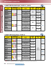
MEASURING LIGHT
SCREENS
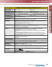
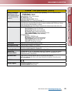
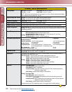
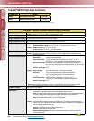
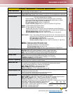
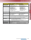
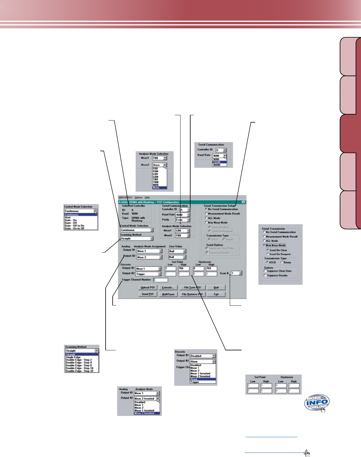
Selected Controller
Identifies the specific control
module being configured.
Serial Transmission
Specifies the type of data transmitted
from the control module to its host after
each scan.
Measurement Mode Result: Data
transmitted will reflect the Analysis Mode
selections.
All Mode: Transmits all data.
Max. Meas. Mode: Sends only the largest
measurement in each measuring event,
to decrease transmission size and speed
response. Choose to send when the array
is clear or send at the host’s request.
Transmission Type: ASCII or Binary,
defines the format in which the data
will be sent.
Serial Options: Suppress Clear Data
or Suppress Header to decrease
transmission size and speed response.
Analysis (Measurement)
Mode Selection
Choose the measurement
option that best tells you the
size and/or position of objects
as they relate to the array.
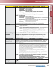
Control Mode Selection
Continuous Mode: The control
module constantly polls
the array for status.
Host Mode: The control module
polls the array for status when
prompted by a host controller.
Gate Mode: The control module
polls the array for status when
prompted by an input from a
Gate sensor.
Scanning Method
Straight scan polls each beam
sequentially to determine the target
object’s overall size. This is the most
accurate and precise measurement,
but also the most time-consuming.
Single Edge scan requires the target
object to block beam 1 (closest to the
sensors’ cabled ends), then conducts
a time-saving binary search to “hunt”
for the target’s overall height (one
variable edge).
Double Edge scan conducts a
binary search of the entire array to
“hunt” for the target’s overall width
(two variable edges).
Set Point and Hysteresis Selection
Assigns the set point to determine where
within the array the output(s) will respond and
hysteresis values to smooth output response.
Trigger/Trigger Channel Number
May be used to trigger (or gate) the scan
sequence of another A-GAGE High-Resolution
MINI-ARRAY controller; in straight scanning
mode, it defines when during each scan discrete
Output #2 will change state.
Scan #: (1-9) Analog outputs are updated with
an average value of the data received during
the selected number of scans; discrete outputs
respond only if the received data is
identical for all of the selected number
of consecutive scans.
Analog and Discrete
Output Assignment
Assigns an analysis
(measurement) mode
to each output.
Alarm: Causes the control module to
turn on discrete Output #2 whenever the
System detects a sensing error or if the
optical signal becomes marginal.
Serial Communication
Changes the identification
and baud rate of the
controller being configured.
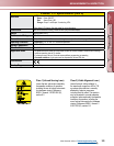
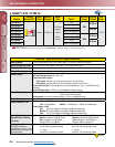
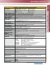
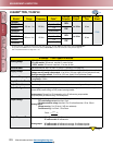
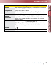
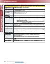
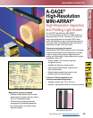
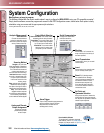
Many options, yet easy to program.
The software included with the control module makes it easy to configure the High-Resolution MINI-ARRAY
®
using your PC-compatible computer*.
Simply load the software, access the program, perform the “Ping” procedure to select the desired controller and access the Edit PSF Configuration
screen, shown below. Each option is easily selectable, using your mouse and the pop-up menu-style selections.
*Running Windows® 95, 98, NT, ME, XP or 2000
Downloadable Software
To test and verify software, download
High-Resolution MINI-ARRAY with blanking
version 1.0 (61330.exe) at
www.bannerengineering.com.
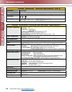
System Configuration