290 More information online at bannerengineering.com
PICK-TO-LIGHT
MEASUREMENT & INSPECTION
TEMPERATURE
ULTRASONIC
LIGHT
GAUGING
RADAR
MEASURING LIGHT
SCREENS
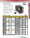
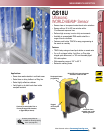
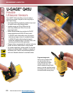
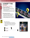
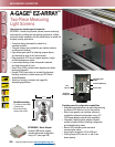
A-GAGE
®
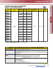
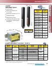
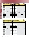
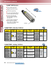
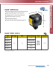
EZ-ARRAY
™
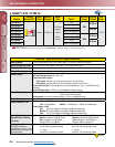
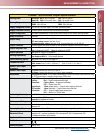
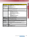
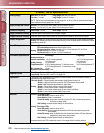
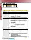
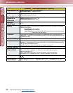
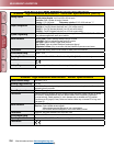
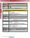
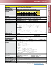
Specification
Supply Voltage (Limit Values)
Emitter: 12 to 30V dc
Receiver Analog Current Models: 12 to 30V dc Receiver Analog Voltage Models: 15 to 30V dc
Supply Power Requirements
Emitter/Receiver Pair (Exclusive of discrete load): Less than 9 watts Power-up delay: 2 seconds
Emitter/Receiver Range
400 mm to 4 m
Field of View
Nominally ± 3°
Beam Spacing
5 mm
Light Source
Infrared LED
Minimum Object
Detection Size
Straight Scan, Low-Contrast: 5 mm
Straight Scan, High-Excess-Gain: 10 mm
Sensor Positional Resolution
Straight Scan: 5 mm Double-Edge Scan: 2.5 mm Single-Edge Scan: 2.5 mm
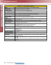
Teach Input
(Receiver Gray Wire)
Low: 0 to 2 volts High: 6 to 30 volts or open (input impedance 22 kΩ)
Two Discrete Outputs
Solid-State NPN or PNP (current sinking or sourcing)
Rating: 100 mA max. each output
OFF-State Leakage Current: NPN: less than 200 uA @ 30V dc PNP: less than 10 uA @ 30V dc
ON-State Saturation Voltage: NPN: less than 1.6V @ 100 mA PNP: less than 2.0V @ 100 mA
Protected against false pulse on power-up and continuous overload or short circuit.
Two Analog Outputs
Voltage Sourcing: 0 to 10V (maximum current load of 5 mA)
Current Sourcing: 4 to 20 mA (maximum resistance load = (V
supply
–3) / 0.020)
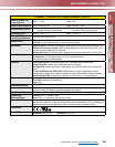
Serial Communication
Interface
EIA-485 Modbus RTU (up to 15 nodes per communication ring)
RTU binary format
Baud Rate: 9600, 19.2K or 38.4K
8 Data Bits, 1 Stop Bit, and Even, Odd, or 2 Stop Bits and No Parity
Scan Time
Scan times depend on scan mode and sensor length. Straight scan times range from 2.8 to 26.5 milliseconds.
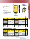
Status Indicators
Emitter: Red Status LED
ON Steady—Status OK Flashing at 1 hz—Error
Receiver:
7 Zone Indicators
Red—Blocked channels within zone Green—All channels clear within zone
3-digit 7-segment indicators for measurement mode / diagnostic information
Sensor Status Bicolor Indicator LED
Red—Hardware Error or Marginal Alignment Green—OK
Modbus Activity Indicator LED: Yellow
Modbus Error Indicator LED: Red
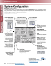
System Configuration
(Receiver Interface)
6-position DIP switch: Used to set scanning type, measurement modes, analog slope and discrete output
2 function. Alternate software GUI interface provides additional options; see full manual (p/n
130426).
Push Buttons
(Receiver Interface)
Two momentary push buttons for alignment and gain level selection.
Connections
Serial communication: The receiver uses a PVC-jacketed, 5-conductor 22-gauge quick-disconnect cable,
5.4 mm diameter. QD cables are ordered separately. See page 422.
Other Sensor connections: 8-conductor quick-disconnect cables (one each for emitter and receiver),
ordered separately (may not exceed 75 m long), PVC-jacketed cables measure 5.8 mm diameter, have
shield wire; 22-gauge conductors. QD cables are ordered separately. See page 416.
Construction
Aluminum housing with clear-anodized finish; acrylic lens cover
Environmental Rating
IEC IP65
Operating Conditions
Temperature: –40° to +70° C Relative humidity: 95% at 50° C (non-condensing)
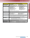
Hookup Diagrams
NPN models: MI23 (p. 537) PNP models: MI24 (p. 537)