


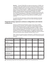
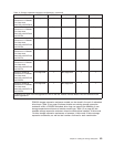

Table 16. Recommended enclosure ID schemes for the first and second redundant drive
loop pair
Enclosure Enclosure ID of
First redundant drive loop
pair
Second redundant drive
loop pair
1
1 00 10
2
2 01 11
3 02 12
4 03 13
5 04 14
6 05 15
7 06 16
8 07 17
1
In the DS4500 configuration with a maximum of 14 EXP810s, the enclosure IDs of the
EXP810s will be automatically set to 0-13.
2
The x10 digit of the enclosure IDs can be any value as long as combining it with the
single-digit value creates a unique enclosure ID in the whole DS4500 configuration, not just
in a given redundant drive loop pair.
Important: Ensure that the single digit (x1) of the enclosure ID for every
enclosure in a redundant drive loop pair is unique. (In addition to expansion
enclosures, this includes any storage subsystem that has drives installed.)
Note: The EXP810 enclosure ID can be changed via the menu option in the
DS4000 Storage Manager subsystem management window only.
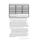
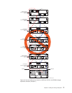
v If it is not possible to avoid mixing different enclosures types in the same
redundant drive loop pair, this rule must be strictly observed. When mixing
EXP810 and EXP710 enclosures in the same drive loop with EXP100
enclosures, all of the EXP810s and EXP710s must be grouped together with the
EXP100 connected to either end of the EXP810/EXP710 drive expansion
enclosure group. The primary reason for this grouping is because the controller
firmware considers the EXP810s and EXP710s to be the same enclosure type
(switched disk expansion unit type which have an ESM-embedded Fibre channel
loop switch) despite being different models. These two enclosure models must be
grouped together if they are contained within a drive loop.
Note:
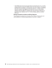
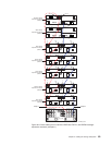
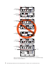
You must cable all of the EXP810 together, then followed by all of the
EXP710 or vice versa. Figure 48 on page 69 and Figure 49 on page 70
are examples of correctly cabling the intermix of EXP100 with EXP810
and EXP710 enclosures. Figure 50 on page 71 and Figure 51 on page 72
are examples of incorrectly cabling the intermix of these enclosures. One
shows the EXP100s cabled between the EXP810s and EXP710s, while
the other shows the EXP810s and EXP710s intermingled, not with the
EXP810s grouped separately from the EXP710s as recommended.
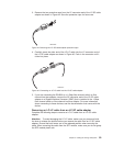
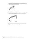
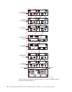
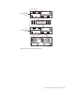
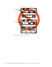
v The DS4500 drive mini hub port must always be connected to the EXP810 port
1B, regardless of whether the port is on the EXP810 ESM A or ESM B. Figure 52
on page 73 is an example of correctly cabling the EXP810 1B ports to the
DS4500 drive mini hub port. Figure 53 on page 74 is an example of incorrect
cabling showing the connection from the drive mini hub port to the incorrect
EXP810 port, labeled 1A.
Chapter 3. Cabling the storage subsystem 67