


2. Replace the protective caps on the cables.
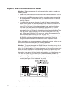
3. Remove the SFP modules from the mini hub as follows:
a. Unlock the SFP module latch by pulling the plastic tab outward 10° and slide
the SFP module out of the mini-hub port.
b. Replace the protective cap on the SFP module.
c. Place the SFP modules into their static-protective packages.
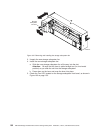
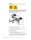
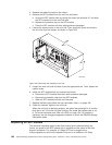
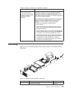
4. Loosen the captive screw on the mini hub. Then, grasp the screw and remove
the mini hub from the chassis, as shown in Figure 109.
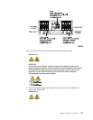
OUT
IN
IN
OUT
IN
!
2Gb/s
1Gb/s
OUT
IN
!
2Gb/s
1Gb/s
GS000039
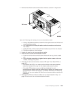
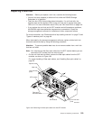
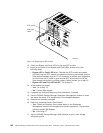
5. Unpack the new mini hub and slide it into the appropriate slot. Then, tighten the
captive screw.
6. Install the SFP modules that you removed as follows:
a. Remove the SFP modules from their static-protective packages.
b. Remove the protective caps from the SFP modules.
c. Slide the SFP modules into the mini-hub ports.
7. Replace the fiber-optic cables that you removed in Step 1 on page 159.
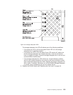
8. Check the indicator lights on the mini hub.
When the mini hub is operating properly, the green loop good light is lit and the
fault light is off. If the mini-hub port is active, the amber port bypass light is not
lit. For more information see “Mini hub LEDs” on page 134. If a problem is
indicated, use the storage-management software to check the DS4500 Storage
Subsystem status.
Replacing an SFP module
The maximum operating speed of the fibre channel port is determined by two
factors: the speed of the SFP module that is installed and the speed of the fibre
channel connection. For example, a 2-Gbps SFP that is plugged into a
4-Gbps-capable port will limit the speed of that port to a maximum of 2 Gbps.
Figure 109. Removing and installing a mini hub
160 IBM TotalStorage DS4500 Fibre Channel Storage Subsystem: Installation, User’s, and Maintenance Guide