


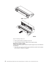

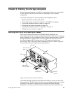
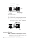
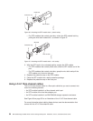
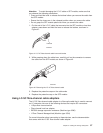

Ethernet interface ports
There are two Ethernet interface ports, one for each controller (Controller A and
Controller B). Use the Ethernet ports to directly manage storage subsystems.
Figure 33 shows the location of these ports.
Note: Note: The default IP address for controller A and B Ethernet ports are
192.168.128.101 and 192.168.128.102, respectively. The default subnet
mask for these ports is 255.255.255.0.
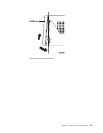
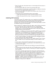
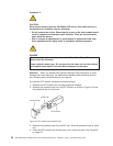
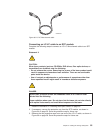
Handling fiber-optic cables
Attention: To avoid damage to your fiber-optic cables, follow these guidelines:
v Do not route the cable along a folding cable-management arm.
v For devices on slide rails, leave enough slack in the cables so they do not bend
to a diameter of less than 76 mm (3 in.), or a radius less than 38 mm (1.5 in.),
when extended or become pinched when retracted.
OUT
IN
!
2Gb/s
1Gb/s
OUT
IN
!
2Gb/s
1Gb/s
OUT
IN
!
2Gb/s
1Gb/s
OUT
IN
!
2Gb/s
1Gb/s
OUT
IN
!
2Gb/s
1Gb/s
OUT
IN
!
2Gb/s
1Gb/s
OUT
IN
!
2Gb/s
1Gb/s
OUT
IN
!
2Gb/s
1Gb/s
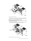
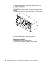
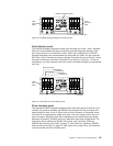
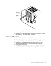
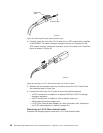
Drive
mini-hub
ports
Drive loop C and D for
redundant drive loop pair 2
Drive loop A and B for
redundant drive loop pair 1
4
Use one port on each
mini hub to connect
a drive loop cable
Leave one port unoccupied
for future upgrades
GS000043
3
2
1
Figure 32. Drive-side mini hub ports
Figure
33. Ethernet ports
50 IBM TotalStorage DS4500 Fibre Channel Storage Subsystem: Installation, User’s, and Maintenance Guide