


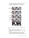
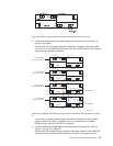
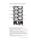
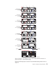

Leave port 1A on the ESM B board on the last (fourth) storage expansion
enclosure and the Out (upper) port on drive mini hub 2 unoccupied.
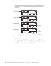
To connect a second redundant storage expansion enclosure group to the
DS4500 Storage Subsystem, continue with Step 3.
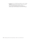
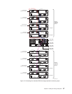
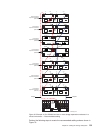
3. Connect drive loop C to the DS4500 Storage Subsystem, as shown in Figure 74
on page 97.
Starting with the first storage expansion enclosure in group 2, connect port 1B
on the ESM A board to the Out (upper) port on drive mini hub 3.
Leave port 1A on the ESM A board on the last (fourth) storage expansion
enclosure in group 2 and the In (lower) port on the drive mini hub 3 unoccupied.
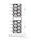
4. Connect drive loop D to the DS4500 Storage Subsystem, as shown in Figure 74
on page 97.
Starting with the last storage expansion enclosure in group 2, connect port 1B
on the right ESM B board to the In (lower) port on mini hub 1.
EXP810
ESM B
ESMA
EXP810
ESM B
ESMA
EXP810
ESM B
ESMA
EXP810
ESM B
ESMA
Port 1B
Port 1B
Port 1A
Port 1B
Port 1A
Port 1A
Port 1B
Port 1A
Port 1B
Port 1B
ds4500_8107
Loop B
Loop A
First storage
expansion enclosure
Second storage
expansion enclosure
Third storage
expansion enclosure
Fourth storage
expansion enclosure
Port 1A
Port 1B
Port 1A
Port 1B
Drive-side
mini hub 4
Drive-side
mini hub 2
Figure 73. Connecting redundant EXP810 drive loops to the DS4500
Chapter 3. Cabling the storage subsystem 95