


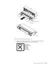
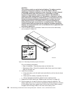
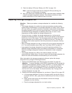
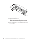
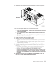
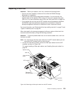

2. Remove the failed fan and communications module, as shown in Figure 105.
a. Using a flat-blade screwdriver, loosen the two captive screws on the fan and
communications module.
b. Lift up and pull out on the pull handle to slide the module out of the slot a
few inches.
c. Grasp the sides of the module with both hands and pull it from the chassis.
d. Place the module on a level surface.
3. Unpack the new fan and communications module.
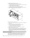
4. Install the new fan and communications module:
a. Push the new fan and communications module all the way into its chassis
slot.
b. Use a flat-blade screwdriver to tighten the two captive screws on the new
module, securing it into place.
5. Check the fan and communications module LED (see “Front Bezel LEDs” on
page 127).
v If the amber fault LED is on, make sure that the fan and communications
module is inserted all the way into the chassis and secured in place.
v If the fault LED remains on, one or both fans inside the fan and
communications module might be malfunctioning. Replace the failed fan and
communications module with a spare, if available. Otherwise, shut down the
DS4500 until you can replace the failed fan and communications module with
a new one.
6.
Reconnect the Ethernet interface cables that you disconnected in Step 1 on
page 154 to the new fan and communications module.
Figure 105. Removing and installing a fan and communications module
Chapter 5. Replacing components 155