


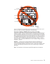
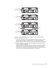
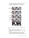
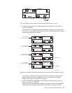

Starting with the first storage expansion enclosure in the loop, connect the Out
port on the right ESM board to the In (lower) port on drive mini hub 2.
Leave the In port on the right ESM board on the last storage expansion
enclosure and the Out (upper) port on drive mini hub 2 unoccupied.
To connect a second redundant storage expansion enclosure group to the
DS4500 Storage Subsystem, continue with Step 3.
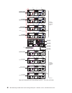
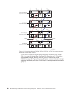
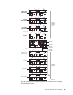
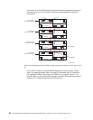
3. Connect drive loop C to the DS4500 Storage Subsystem, as shown in Figure 66
on page 89.
Starting with the first storage expansion enclosure in group 2, connect the In
port on the left ESM board to the Out (upper) port on drive mini hub 3.
Leave the Out port on the left ESM board on the last storage expansion
enclosure in group 2 and the In (lower) port on the drive mini hub 3 unoccupied.
First storage
expansion enclosure
Third storage
expansion enclosure
Right ESMLeft ESM
Out
Out
In
d3nu4044d
Right ESMLeft ESM
Out
Out
In
Second storage
expansion enclosure
Right ESMLeft ESM
EXP500/100/7x0
In
In
Out
Out
In
Right ESMLeft ESM
Out
Out
In
Fourth (last) storage
expansion enclosure
In
In
EXP500/100/7x0
EXP500/100/7x0
EXP500/100/7x0
LoopA Loop B
Drive-side
mini hub 4
Drive-side
mini hub 2
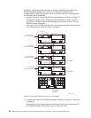
Figure 65. Connecting redundant EXP500, EXP100, EXP700, or EXP710 drive loops to the
DS4500
Chapter 3. Cabling the storage subsystem 87