


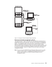
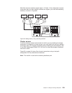
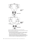
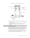

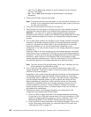

See Figure 85 for an example of redundant power cabling.
6. Go to “Powering on the storage subsystem” on page 119 for the initial startup of
the storage subsystem.
Attention: Before you power on the storage subsystem, any storage
expansion enclosures should be completely connected to the storage
subsystem.
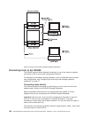
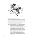
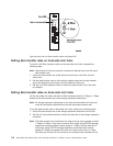
Setting the Link Rate Interface switch
Each DS4500 Storage Subsystem mini hub has a Link Rate Interface switch that is
used to select the host-side or drive-side mini-hub data transfer rates. The switch
settings are labeled 2 Gb per second and 1 Gb per second. Use a device with a
point such as a small flat-blade screwdriver or ballpoint pen to set the host-side or
drive-side mini hub Link Rate Interface switch. See Figure 86 on page 114.
The Speed LED is green when the data transfer rate of the fibre channel loop is 2
Gbps. The Speed LED is off when the data transfer rate is 1 Gbps. Figure 86 on
page 114 shows the location of the Link Rate switch and LED.
AC distribution unit
power cord
Controller power supplies
Storage expansion
enclosure
power supplies
Rack power cable connector
Rack power cable
AC distribution units
f10ug060
Figure 85. Redundant AC power connections to controllers and storage expansion enclosures
Chapter 3. Cabling the storage subsystem 113