


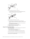

Host interface ports
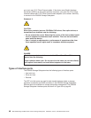
The DS4500 Storage Subsystem comes with host-side mini hubs 1 and 2 installed.
Each mini hub provides host loop connectivity and self-diagnostic features. Host
mini hubs connect to the controller in pairs. When fully configured, the DS4500
Storage Subsystem can accommodate four host-side mini hubs, two per controller.
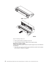
Mini hubs 1 and 3 connect to the top controller (Controller A) and mini hubs 2 and 4
connect to the bottom controller (Controller B), as shown in Figure 31. To ensure
redundancy, you must connect each host to both controllers through the appropriate
mini hub.
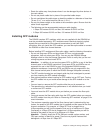
Host mini hubs
Host
mini-hub
ports
Controller A
Controller B
Controller A
Controller B
1234
GS000042
Drive interface ports
The standard DS4500 Storage Subsystem ships with drive-side mini hubs 2 and 4
installed. (In previous releases, the DS4500 was shipped with the drive-side mini
hubs installed in slots 1 and 2.) Each drive mini hub connects to Controller A and
Controller B and represents a single drive loop. The drive loops must be set up in
pairs to support redundant drive loop configurations (two data paths per storage
expansion enclosure). DS4500 uses only redundant drive-loop configurations. For
information about cabling the DS4500 drive loops, see “Overview: Cabling a
DS4500 with two drive mini hubs” on page 77 and “Overview: Cabling a DS4500
with four drive mini hubs” on page 79. See Figure 32 on page 50 for an illustration
of the drive-side mini-hub interface ports.
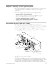
Host
mini-hub
ports
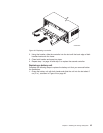
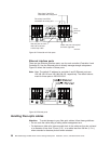
Ethernet interface ports
Drive
mini-hub
ports
GS000041
Figure 30. DS4500 Storage Subsystem interface ports
Figure
31. Host-side mini hub interface ports
Chapter 3. Cabling the storage subsystem 49