


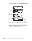

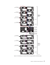
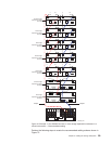
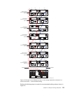
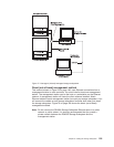
1. Connect the storage expansion enclosures to drive loop A as follows:
a. Starting with the first storage expansion enclosure, connect a fiber-optic
cable from port 1B on the ESM A board to port 1A on the ESM A board in
the second enclosure.
Leave port 1A on the ESM A board in the first enclosure unoccupied.
b. Connect port 1B on the ESM A board in the second enclosure to the Out
port on the left ESM in the third enclosure.
c. Connect the In port on the left ESM in the third enclosure to the Out port on
the left ESM in the fourth enclosure.
d. Connect the In port on the left ESM in the fourth enclosure to the Out port
on the left ESM in the fifth enclosure.
e. Connect the In port on the left ESM in the fifth enclosure to the Out port on
the left ESM in the sixth enclosure.
f. Connect the In port on the left ESM in the sixth enclosure to the Out port on
the left ESM in the seventh enclosure.
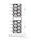
2. Connect the storage expansion enclosures to drive loop B as follows:
a. Starting with the first storage expansion enclosure, connect a fiber-optic
cable from port 1A on the ESM B board to port 1B on the ESM B board in
the second enclosure.
b. Connect port 1A on the ESM B board in the second enclosure to the Out
port on the right ESM in the third enclosure.
c. Connect the In port on the right ESM in the third enclosure to the Out port
on the right ESM in the fourth enclosure.
d. Connect the In port on the right ESM in the fourth enclosure to the Out port
on the right ESM in the fifth enclosure.
e. Connect the In port on the right ESM in the fifth enclosure to the Out port on
the right ESM in the sixth enclosure.
f. Connect the In port on the right ESM in the sixth enclosure to the Out port
on the right ESM in the seventh enclosure.
Leave In port on the right ESM in the seventh enclosure unoccupied.
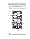
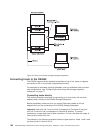
3. Connect drive loop A to the DS4500 Storage Subsystem as follows:
v Connect the In port on the left ESM in the seventh enclosure to the Out
(upper) port on drive mini hub 4 on the DS4500.
Leave the In (lower) port on drive mini hub 4 unoccupied.
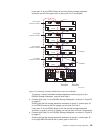
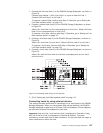
4.
Connect drive loop B to the DS4500 Storage Subsystem as follows:
v Connect port 1B on the ESM B board in the first enclosure to the In (lower)
port on drive mini hub 2 on the DS4500.
Leave the Out (upper) port on drive mini hub 2 unoccupied.
100 IBM TotalStorage DS4500 Fibre Channel Storage Subsystem: Installation, User’s, and Maintenance Guide