


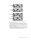
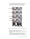
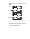
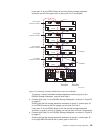

2. Connect the same first two storage expansion enclosures to drive loop B, as
shown in Figure 69.
Starting with the first storage expansion enclosure, connect a fiber-optic cable
from port 1A on the ESM B board to port 1B on the ESM B board in the second
(next) storage expansion enclosure.
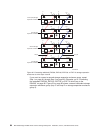
If you want to connect more storage expansion enclosures into drive loops A
and B, continue with Step 3; otherwise, go to “Connecting the redundant
EXP810 drive loop to the DS4500” on page 93.
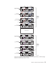
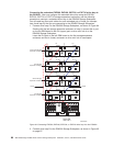
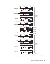
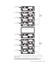
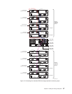
3. Connect additional storage expansion enclosures to drive loops A and B, as
shown in Figure 70 on page 92.
Starting with the second storage expansion enclosure, connect each additional
storage expansion enclosure into drive loops A and B in the same manner.
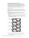
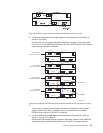
Figure 68. EXP810 storage expansion enclosure ESM board ports 1A and 1B
EXP810
ESM B
ESMA
EXP810
ESM B
ESMA
EXP810
ESM B
ESMA
EXP810
ESM B
ESMA
Port 1B
Port 1B
Port 1A
Port 1B
Port 1A
Port 1A
Port 1B
Port 1A
Port 1B
Port 1B
ds4500_8103
Loop B
Loop A
First storage
expansion enclosure
Second storage
expansion enclosure
Third storage
expansion enclosure
Fourth storage
expansion enclosure
Port 1A
Port 1B
Port 1A
Port 1B
Figure 69. Connecting two EXP810 storage expansion enclosures into redundant drive loop
B
Chapter 3. Cabling the storage subsystem 91