


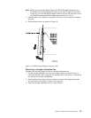

v The lip on the rail should line up with the bottom of the storage subsystem
(the 0 U boundary in Figure 10 on page 29).
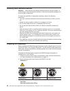
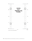
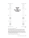
5. Insert the cage nuts or the slide clip nuts, as required for the rack, into all of
the marked holes. Use the cage nut insertion tool or a flat-blade screwdriver to
insert cage nuts.
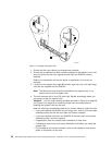
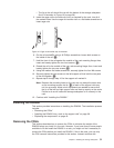
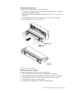
6. On the rail marked R, using a #2 Phillips screwdriver, loosen both screws on
the inside of the rail (1).
7. Hold the front of the rail against the outside of the rack mounting flange; then,
insert and loosely tighten the two front screws (2).
8. Extend the rail to the outside of the rear rack-mounting flange; then, insert and
loosely tighten the two rear screws (3).
9. Using the medium flat blade screwdriver, securely tighten the four M6 screws.
10. Securely tighten the two screws on the left support rail that hold the two parts
of the rail together (1).
11. Repeat step 6 through step 10 for the support rail marked L.
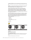
Note:
Because the mounting holes on the rack are not always the same size
as the mounting screws, the lip (4) of each of the support rails may
not line up evenly. Make minor adjustments as needed to ensure that
the lip of the left and right support rails are lined up evenly on the racks.
Failure to do so will cause the storage subsystem to fit unevenly in the
rack.
12. Continue with “Installing the DS4500.”
Installing the DS4500
This section provides instructions on installing the DS4500. The installation process
includes:
v “Removing the CRUs”
v “Installing the DS4500 into a rack on the support rails” on page 38
v “Replacing the components” on page 40
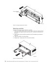
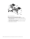
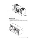
Removing the CRUs
This section describes how to remove the CRUs to minimize the weight of the
DS4500 before you install it in the rack. However, if you have three or more people
available to lift and install the DS4500 in a rack, you might not find it necessary to
remove the CRUs before you install the DS4500. If this is the case, you can skip
the CRU removal instructions provided in this section. Instead, continue with
Cage
nut
Clip
nut
Figure 12. Cage nut and slide clip nut insertion
Chapter 2. Installing the storage subsystem 31