


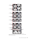
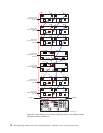
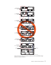
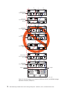
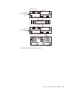
Note: This section also refers to the cabling diagrams in “Storage expansion
enclosure cabling diagrams” on page 68.
The following are general rules or limitations to follow as a guideline when you
connect storage expansion enclosures to the storage subsystem:
v The DS4500 Storage Subsystem supports the connection of a maximum of two
redundant drive loop pairs. The maximum number of drive enclosures per drive
loop depends on the type of storage expansion enclosure and whether
intermixing storage expansion enclosures of different drive slots. For detailed
information, see Table 13 on page 62 and Table 15 on page 65.
v The DS4500 currently supports a maximum of 110 drives in 11 10-drive storage
expansion enclosures or 112 drives in either eight 14-drive or seven 16-drive
storage expansion enclosures per drive loop in each controller. Two drive loops
from the DS4500 drive mini hubs must be connected to the same set of storage
expansion enclosures to provide drive loop redundancy.
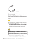
v When connecting the storage expansion enclosures to DS4500 drive mini hubs,
do not use all ports in each of the drive mini hubs. Connect the FC cable to only
one port of the drive mini hub and leave the other port unoccupied.
v When cabling different types of storage expansion enclosures, if possible, do not
mix different types of storage expansion enclosures in the same redundant drive
loop pair. Also, when mixing different types of storage expansion enclosures in
the same drive channel pair, the Link Rate Setting must be the same for each
storage expansion enclosure. IBM does not support different enclosure speed
settings in the same drive loop.
In
addition to the previously outlined general rules, it is strongly
recommended that you observe the following rules when connecting storage
expansion enclosures to the storage subsystem:
v Ensure that the single digit (x1) of the enclosure ID for every enclosure in a
redundant drive loop pair is unique. (In addition to expansion enclosures, this
includes any storage subsystem that has drives installed.)
Enclosure IDs (sometimes known as tray IDs) consist of two digits (x10 and x1).
In 14-drive expansion enclosures (EXP100/EXP700/EXP710), the enclosure ID
may be set manually. In 16-drive expansion enclosures (EXP810), the enclosure
ID is set automatically by the EXP810 ESM and the controller firmware. Please
refer to the Installation, User’s, and Maintenance Guide of your appropriate
enclosures for information on how to manually set the switches.
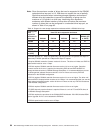
If you do not set the enclosure IDs to be unique among enclosures, then drive
loop errors might be randomly posted in the DS4500 subsystem Major Event Log
(MEL) when intermixing different types of storage expansion enclosures in a
redundant drive loop pair, such as an EXP100 with an EXP810. For example,
with four enclosures attached to the DS4500 in a redundant drive loop pair, the
correct enclosure ID settings should be x1, x2, x3, and x4 (where x can be any
digits that can be set). Examples of incorrect settings would be 11, 21, 31, and
41; or 12, 22, 32 and 62. These examples are incorrect because the x1 digits
are the same in all enclosure IDs (either 1 or 2).
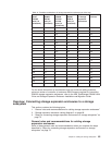
If the enclosure IDs in your DS4000 subsystem configuration are not currently set
to have unique single digit values for the enclosures in the same redundant drive
loop pair, make the changes to the enclosure IDs in the next maintenance
schedule. This will prevent unnecessary downtime when you add enclosures of
different type (especially EXP810s) to the existing enclosures in the redundant
drive loop pair.
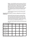
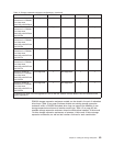
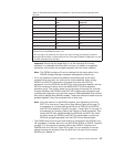
Table 16 on page 67 displays the recommended enclosure ID schemes for the
first and second redundant drive loop pair.
66 IBM TotalStorage DS4500 Fibre Channel Storage Subsystem: Installation, User’s, and Maintenance Guide