


Overview: Cabling a DS4500 with four drive mini hubs
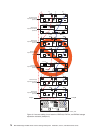
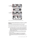
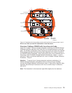
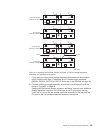
Figure 55 on page 77 shows a storage subsystem containing one DS4500 Storage
Subsystem and two redundant drive loops with four storage expansion enclosures
each. The DS4500 configuration shown requires four drive mini hubs to be installed.
Each storage expansion enclosure group uses redundant drive loops to connect to
the DS4500 Storage Subsystem. Loop A and loop B make up one redundant pair of
drive loops, which is labeled “Storage Expansion Enclosures - Group 1.” Loop C
and loop D make up a second redundant pair, which is labeled “Storage Expansion
Enclosures - Group 2.”
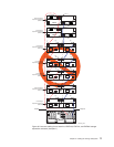
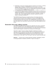
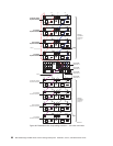
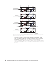
Attention: To prevent loss of storage expansion enclosure redundancy in a
DS4500 Storage Subsystem configuration with four drive mini hubs installed,
connect the storage expansion enclosures as shown in Figure 58 on page 80. Note
especially that drive loop B connects to mini hub 2 and drive loop C connects to
mini hub 3.
Note:
The illustrations in this document might differ slightly from the hardware.
First storage
expansion enclosure
Right ESMLeft ESM
Out
Out
In
ds452mind
Right ESMLeft ESM
Out
Out
In
Last storage
expansion enclosure
In
In
LoopA Loop B
Drive-side
mini hub 2
DS4500
Storage Subsystem
Drive-side
mini hub 1
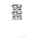
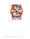
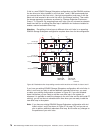
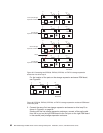
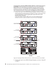
Figure 57. Redundant drive loop cabling overview with two drive mini hubs in slots 1 and 2 -
Not for use unless you meet the requirements in the Note above
Chapter 3. Cabling the storage subsystem 79