


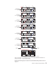
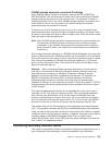
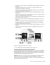
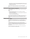

1. Connect the first host (Host 1) to the DS4500 Storage Subsystem, as shown in
Figure 79.
Connect Host Adapter 1 (HA1) from Host 1 to a port on host mini hub 1.
Connect HA2 from Host 1 to mini hub 2.
To connect a second host, continue with Step 2. Otherwise, go to “Setting the
Link Rate Interface switch” on page 113.
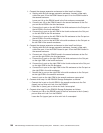
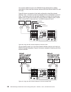
2. Connect a second host (Host 2) to the DS4500 Storage Subsystem, as shown
in Figure 79.
Attach HA1 from Host 2 to the unoccupied port on mini hub 1. Attach HA2 from
Host 2 to the unoccupied port on mini hub 2.
To connect a third host, continue with Step 3. Otherwise, go to “Setting the Link
Rate Interface switch” on page 113.
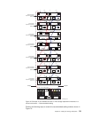
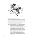
3. Connect a third host (Host 3) to the DS4500 Storage Subsystem, as shown in
Figure 79.
Attach HA1 from Host 3 to mini hub 3. Attach HA2 from Host 3 to mini hub 4.
To connect a fourth host, continue with Step 4. Otherwise, go to “Setting the
Link Rate Interface switch” on page 113.
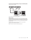
4. Connect a fourth host (Host 4) to the DS4500 Storage Subsystem, as shown in
Figure 79.
Attach HA1 and HA2 from Host 4 to the two unoccupied ports on mini hub 3
and mini hub 4.
5. Go to “Setting the Link Rate Interface switch” on page 113.
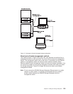
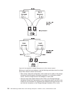
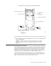
Connecting hosts by using external devices
This section provides instructions for connecting five or more hosts to the DS4500
Storage Subsystem. When you use external fibre channel switches, the DS4500
Storage Subsystem supports up to 64 hosts (128 host adapters, 64 host adapters
per controller) and two host adapters for each host.
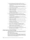
Important: Host mini hub 1 and host mini hub 3 correspond to Controller A (top).
Mini hub 2 and mini hub 4 correspond to Controller B (bottom). To ensure
redundancy, connect each host to both controllers. You can use either the upper or
lower connectors on either mini hub.
Figure 79. Connecting hosts directly to the controller
Chapter 3. Cabling the storage subsystem 107