


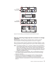
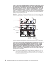

If this is a new DS4500 Storage Subsystem configuration and the DS4500 contains
the two drive mini hubs installed in mini hub slots 1 and 2, IBM recommends that
you remove the mini hub from slot 1 (the right most-position) and swap it with the
blank mini hub inserted in drive mini hub slot 4 (the leftmost position). Then cable
the storage expansion enclosures as shown by “Storage Expansion Enclosures -
Group 1” in Figure 56. By swapping these mini hubs, you will not need to schedule
down time later for re-cabling the drive loop if additional mini hubs are installed to
enable a second redundant drive loop.
Attention: Re-cabling of drive loops to different drive mini hubs in an operating
DS4500 Storage Subsystem configuration requires down time for the configuration.
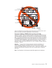
If you have an existing DS4500 Storage Subsystem configuration with mini hubs in
slots 1 and 2 and you plan to add an additional redundant drive loop, you must
re-cable your existing configuration as shown in Figure 56. If you can schedule
down time before you are ready to add the new drive loop in the system (or
whenever it is possible to make the changes to the mini hubs and the drive side FC
cabling), you will not have to schedule down time when you are ready to add the
new drive loop in the system.
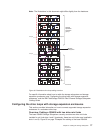
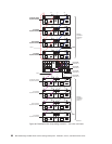
Note: If you have an existing DS4500 Storage Subsystem configuration with mini
hubs in slots 1 and 2 (as shown in Figure 57 on page 79), and you do not
plan to add an additional redundant drive loop, do not make any changes to
the positions of your mini hubs.
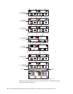
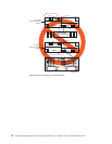
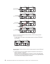
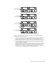
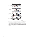
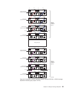
First storage
expansion enclosure
Right ESMLeft ESM
Out
Out
In
ds452minc
Right ESMLeft ESM
Out
Out
In
Last storage
expansion enclosure
In
In
LoopA Loop B
Drive-side
mini hub 4
Drive-side
mini hub 2
DS4500
Storage Subsystem
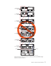
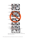
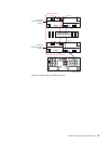
Figure 56. Redundant drive loop cabling overview with two drive mini hubs in slots 4 and 2
78 IBM TotalStorage DS4500 Fibre Channel Storage Subsystem: Installation, User’s, and Maintenance Guide