


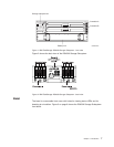
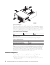

Mini hubs
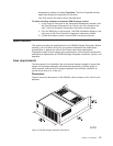
The mini hubs are located on the back of the DS4500 Storage Subsystem (see
Figure 2 on page 7). A mini hub is a single, removable unit that provides the Fibre
Channel interface between a DS4500 and hosts or drive expansion enclosures. The
back of the DS4500 can accommodate eight mini hubs: up to four host-side and up
to four drive-side mini hubs. The standard DS4500 Storage Subsystem ships with
two mini hubs installed in host-side mini hubs slots 1 and 2 and two mini hubs
installed in drive-side mini hubs slots 4 and 2. Each mini hub has two ports. An SFP
module is installed in a mini-hub port; then, a fiber-optic interface cable is
connected into the SFP module. For more information, see “Working with SFPs and
fiber-optic cables” on page 47.
Note: Although the drive-side mini hubs have two ports, only one of the ports are
used for drive loop connection. The other port must be left empty, with no
SFP module inserted and no FC connection made to the port.
Fan and communications module
The fan and communications module is a single, removable unit that contains two
cooling fans and two Ethernet ports. This module plugs into a slot at the center
back of the DS4500 Storage Subsystem, just above the power supplies (see
Figure 2 on page 7). There are two captive screws and a rectangular handle for
securing and removing the module. The module contains dual fans that provide a
redundant cooling system to both power supplies. If one fan within the module fails,
the other continues to operate. A single fan provides sufficient air circulation to
prevent the power supplies from overheating until you can replace the entire fan
and communications module.
Power supply
The DS4500 Storage Subsystem power system consists of two power supplies. The
power supplies slide into either of the two slots on the back of the DS4500 (see
Figure 2 on page 7). The power supplies provide power to the internal components
by converting incoming ac voltage to dc voltage. The power supplies are
interchangeable and redundant. Each power supply uses one power cord. It is
recommended that you plug each cord into a separate circuit for power redundancy.
One power supply can maintain electrical power to the DS4500 if the other power
supply is turned off or malfunctions.
Software and hardware compatibility and upgrades
The latest DS4000 controller firmware and NVSRAM, the storage expansion
enclosure drive enclosure ESM firmware, and the fibre channel drive CRUs
firmware must be installed to ensure optimal functionality, manageability, and
reliability.
Software and firmware support code upgrades
To enable support for the DS4500, you must ensure that your system's software
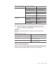
and firmware are at the levels shown in Table 2:
Table 2. Software and firmware levels for the DS4500 Storage Subsystem
Software/firmware Level
DS4000 Storage Manager
software
9.19
10 IBM TotalStorage DS4500 Fibre Channel Storage Subsystem: Installation, User’s, and Maintenance Guide